01
May
20

Musical Box

I’ve always wanted a pianola/player piano, but have never been able to afford one.  Conlon Nancarrow was the original and most famous composer who used a player piano to compose works which were impossible for humans to play – too many notes, too widely spread across the keyboard, and too fast.

I wasn’t quite thinking of emulating that, but I thought it would be interesting to compose by making holes in a strip of card, which is what you have to do with the types of musical boxes which are available.

A quick look at eBay shows there are several variations.  Aside from this type, which plays a fixed tune, either manual:

or wind-up:

there are several types which are, as it were, ‘programmable’, meaning you can create your own tunes to play on them.  The usual ones are 15-note (top of the picture) or 30 note (bottom of the picture):

The 30 note type shows how the thin card strip feeds through the mechanism.  The top roller is the guide and the bottom roller with the ‘spikes’ is the one that plays the notes.

I was rather attracted by a 30 note type which was already installed inside an attractive wooden box:

You can see the slot on the front of the box where the card is fed into the mechanism.  It emerges through a similar slot on the other side. The mechanism itself can be accessed by opening the lid of the box:

It was rather more expensive than the mechanism just by itself, but I thought, well, it looks so much nicer, and the box will act as a sounding board, to improve the sound of the instrument as it plays.

The cost for this one was £29.99, including postage from China, but you can get the mechanism without the box for £22.  They usually come with a few card strips and a special hole-punch, but you’ll need extra strips, which cost around £5 for 10 strips of 75cm – there’s a limit to how fast you can wind the musical box, so I’d estimate you wouldn’t get much more than 30 seconds of music from a strip of that length.

This is what the strips look like:

but to save you having to join strips together – although this isn’t difficult, as I describe below – you can also get a continuous 10m strip like this:

*

The king of the musical box is undoubtedly Martin Molin of the Swedish group Wintergatan.  Perhaps better known as the inventor of the wonderful Marble Machine, Martin has also posted a number of videos on YouTube about his work with a 30-note musical box, including details of its construction and making the punched-hole card strips which play the tunes.  Here’s an example which begins with a great view of the musical box live on stage.

I watched all the videos carefully, and was concerned by Martin’s comments on the problems he had with reliability, which he put down to the plastic cogs in the mechanism.  You can see those in the picture above.

As a result of that, I decided to bite the bullet and buy a set of metal replacement cogs.  These came from the UK, but were still £13.33 including postage, so this was becoming rather an expensive project.  However, the one 30-note mechanism I saw which already had metal cogs was £55, so I suppose buying my own had saved a bit of money . . .

The advert said they were made of copper, although they were surely brass, which would be the normal materal for such things.  When they arrived, they were clearly precisely the correct set for this mechanism, matching the dimensions of the plastic ones exactly, and even included replacement screws and washers, which wouldn’t be needed if the originals were retained during dismantling.

The instructions for replacement were included in the eBay listing, a series of very clear pictorial illustrations of the procedure.  I was a bit concerned before I started, as I wasn’t sure if it would be as easy as it looked in the pictures – but it was!

The mechanism was attached to the box by 4 screws on the underside.

To take it out, these 4 screws needed removing, plus two screws on the inside, which attached the handle to the main part of the mechanism.

Removal of the plastic cogs was easy, requiring a little work with fine-nosed pliars  – I also need them to pull off the ones which are shown here being removed by hand: they were on a little too tightly to do that.

Likewise, putting the new cogs in.  In a couple of cases, this was just a matter of putting them in place, bending the retaining arm back into position in one case, and replacing a small clip in another.

Even the ones on the rollers, which had to be gently hammered into position, were easily done in exactly the way shown in the instructions.  Resting the assembly on a nut, it was possible to move the new cog slowly into place by tapping on the top.

I gave the new cogs a light spray with WD40 before reassembling the mechanism in the box.

[Edit: following a comment made below, I bought some proper clock oil to use instead of WD40 – a wonderful cleaner, but not a proper lubricant, and can attract water, dust and dirt.  There are many different types available, but one I bought was this one:

Processed By eBay with ImageMagick, z1.1.0. ||B2

The cost was only £3.50, and regular use will keep the new cogs turning smoothly.]

Everything fitted precisely, and the only give in the system turned out to be the base of the box, which was loose and moved slightly while the mechanism was being wound.  This was soon cured with a couple of spots of superglue.

I tried the new arrangement out, and it worked perfectly.  With luck, this should now be sufficiently robust for me not to have to worry about slipping or jamming when I’m trying to play music.

*

Next, then, I needed to work on some punched-hole strips to play some music.  It seemed to me that there were 3 things I could do: firstly, transcribe some music I had already written; secondly, write some new pieces especially for the musical box; and thirdly, create some music unique to the instrument by punching random holes, or holes in patterns where part of the pleasure would come from not knowing what it would sound like until fed into the machine!

*

The beginning of the strip was printed with the 30 notes, and a helpful indication of which direction the strip should travel:

The first thing which is apparent is that the 30 notes are not a continuous two and a half octave scale.  Looking carefully, you can see nearly two octaves of continuous notes from E1 to C3; below E1 there are 7 ‘bass’ notes, extending just over an octave below; above C3 there are just 2 higher notes; so there is a range of just over 3 octaves, but with some notes missing – principally sharps or flats – meaning that some keys will more easily able to use the full range of notes than others.

The format of the card strip is simple enough: each of the 30 notes is represented by one of the 30 lines that runs the length of the strip.  Make a hole at a certain point on that line and the corresponding note will sound.

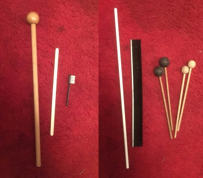
A special hole-punch which was suitable for this job was included with the kit:

There are lots of nice punches out there that can make 2mm holes, like these:

but they’re all useless, as the card strips are 70mm (7cm/2¾”) wide, so the punch needs jaws of at least 35mm depth, and preferably more: the hole-punching part of the exercise is very tedious, and the deeper the jaws of the punch, the easier this job is going to be.  The supplied punch allows you to reach about 50mm across the strip, which is most of the way, if not all the way, and was, in fact, far enough for most of what I did, without having to turn the strip around and finish off punching from the other side.

*

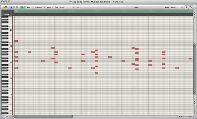
To start with the transcription of pieces I had already written, I turned to the application Logic, where they had for the most part been written.  One of the views you can have of a piece in Logic is called the ‘piano roll’.  This looks exactly like the strip above, with the lowest note at the bottom, the highest note at the top, and a dot (for a short note) or a line (for a long note) in exactly the place where it needs to sound.

I found some suitable pieces which were written wholly or mainly for a single instrument and turned to the piano roll view.  Typically, it might look like this screenshot, with short notes represented by a short line, longer notes represented by a longer line; the piano keyboard on the left-hand side indicated which note was which:

There were two things I had to do with this representation of the piece for it to be of use to me in preparing the card strips.

First of all, I had to remove or reposition notes so there were none outside the range of the musical box – the piece above, while perfectly OK on the piano, has notes which are both too high and too low for the musical box.

This is an example of a section where all the notes have been adjusted to fall within the musical box’s range:

Secondly, as the musical box doesn’t distinguish between short notes and long notes, I needed to reduce the length of the lines so they were all very short, like the holes that I would be making in the strips.

This is what the piece looked like when I had done that:

In this way I had reasonably quickly come up with a template which I could copy onto a strip, and hopefully reproduce – albeit slightly simplified – a piece I had already written.

I printed out the screenshots:

and started copying the dots in the screenshots onto the card strip.

Soon after I started marking dots on the card strip, I found this to be a useful tool (the one on the right if you’re left-handed):

This is the guide to the notes cut off the left-hand end of a strip; the one on the right is from the right-hand end.

The problem is that while you’re near the beginning of the strip, it’s easy to see which line corresponds to which note; but the further away you get from the end, the harder it is to see which note is which.  The first piece I finished used several strips joined together, and was about 2 metres long.  It would be pretty well impossible to keep looking back to the end to work out where to place a mark or punch a hole, so using this indicator in one hand, while I marked the dots with the other was very helpful for making sure I chose the right note.

The further I got from the left-hand end, the more useful this tool became; and eventually, as I implied above, I had to extend the strip by joining another one onto it.

I decided the best way to do this was somewhat like splicing audio or video tape, which we don’t do now, but used to have to do years ago.  So, my recommended method is to cut off the end of the new strip – the part with the notes on it can be put aside for a new tool when marking dots in future, and the remaining part trimmed along a easily identifiable line:

This strip can then be stuck over the strip you’re coming to the end of.  The edge should be matched precisely with the existing strip, and the two strips should overlap so that a diagonal line can be drawn at about 45° across the part where the two strips overlap.

The picture shows the strips temporarily stuck together with masking tape.  I used masking tape for this job because it’s not too sticky – especially for this first join, which is temporary; it’s see-through, so it won’t  stop you adding new dots when you continue work later; and it’s quite thin, so it won’t cause the strip to get jammed in the musical box mechanism.  The arrows indicate the area where the two strips overlap, and the diagonal line is shown in between them.

To finish off, cut along the diagonal line with craft knife or scissors, undo the temporary join and fix the two strips together, end-to-end, with no overlap.  I only used masking tape on one side for this as putting tape on both sides of made the card rather thick and it wasn’t going through the musical box mechanism very easily.

I decided to stop after every page of screenshots, having marked in the dots, and punch the holes, so I didn’t have a huge amount of hole-punching to do at the end.

One piece of advice I would have at this stage – and I only realised this after starting and having to clear up the mess on my carpet! – is to use a tray or something like that to catch the tiny dots of card removed by the hole punch.  This is the result of just part of the hole punching for this first piece:

However, after joining a couple of new strips to my original one I had marked all the dots for the complete piece, and finished punching the holes.

This was the moment of truth – I fed the strip into the musical box and wound the handle . . . and, sure enough, the sound that came out definitely resembled the piece I had written!

*

The first experimental piece was pretty straightforward – I punched out my name on a card strip:

Letters of the alphabet are not ideal for this purpose, because they contain a lot of vertical lines (many notes played at once), horizontal lines (the same note repeated many times) and diagonal lines (scales up or down), and not much in the way of tunes; however, this was a reasonable start!

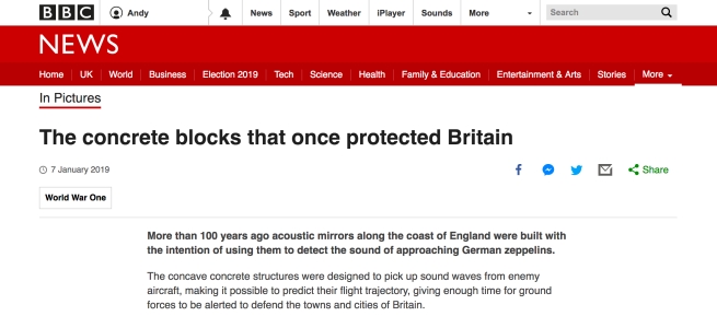
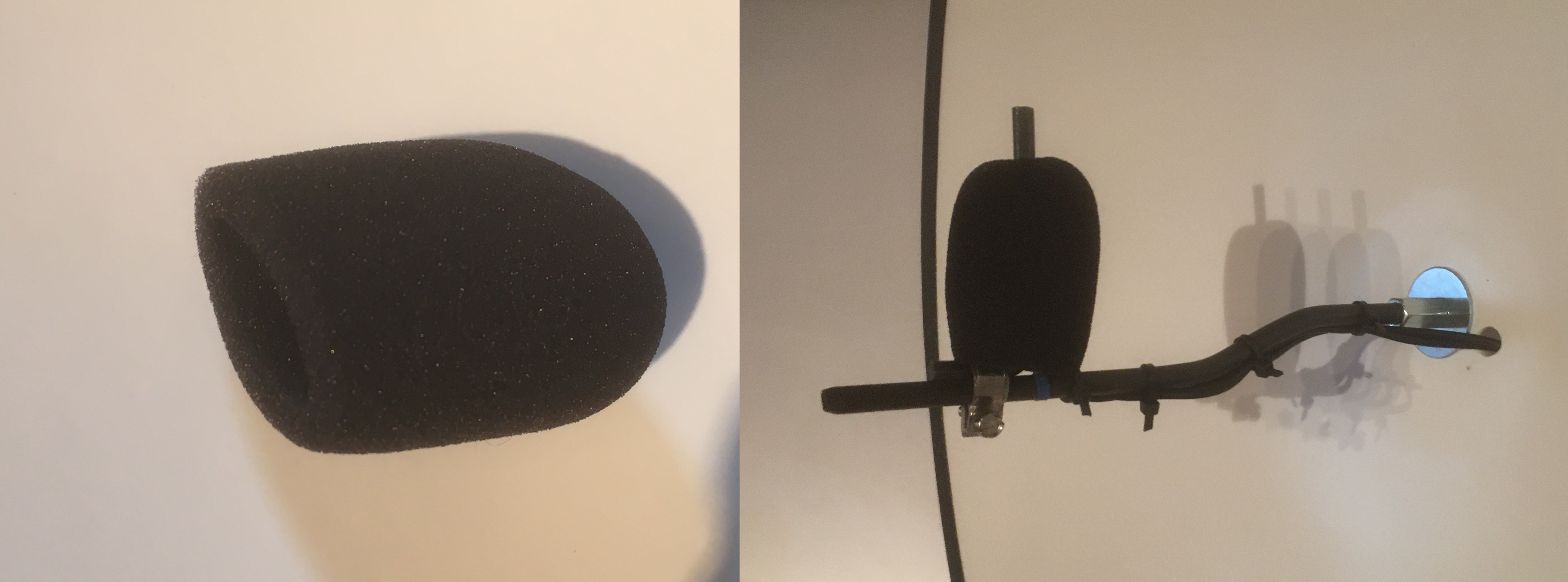
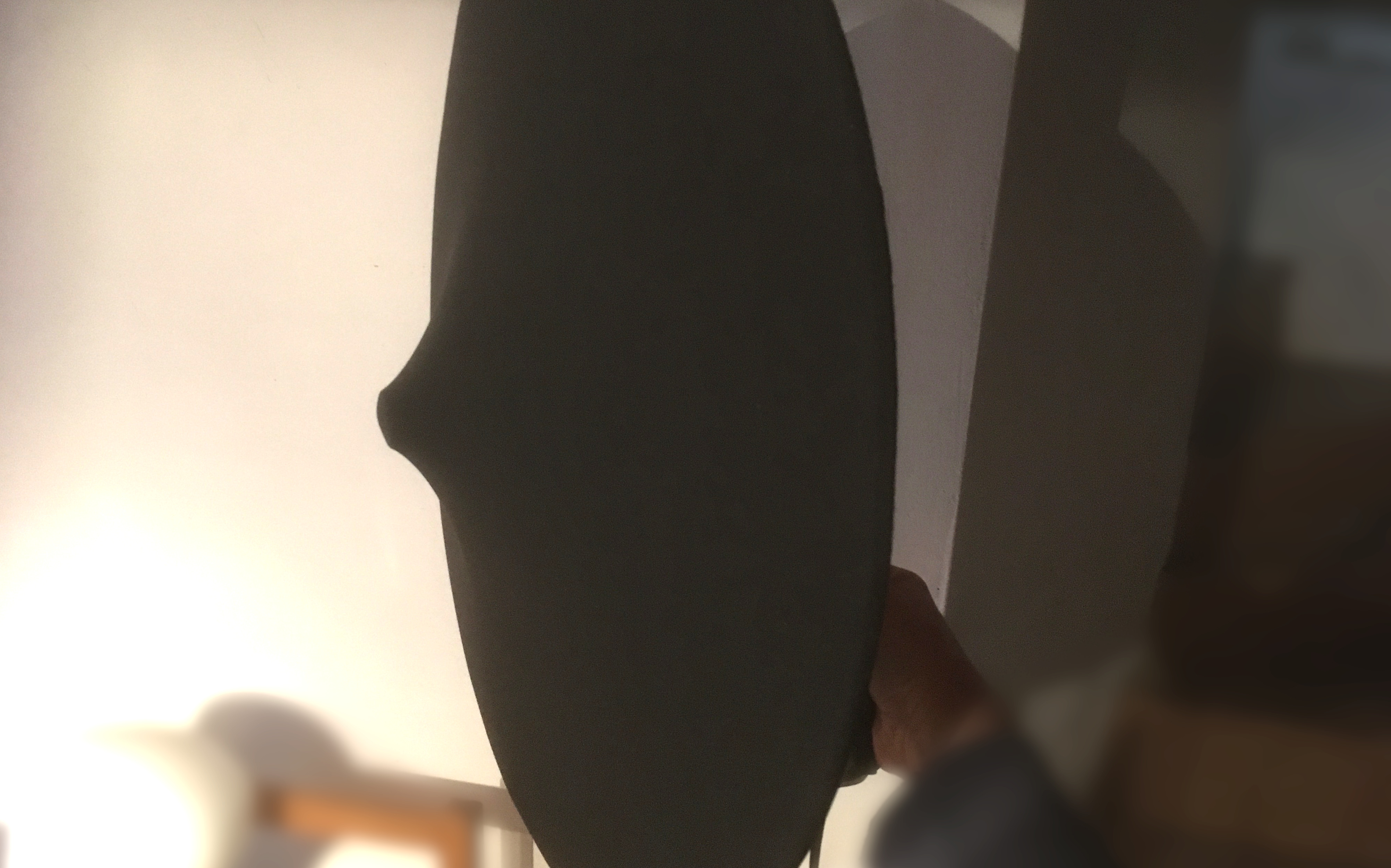
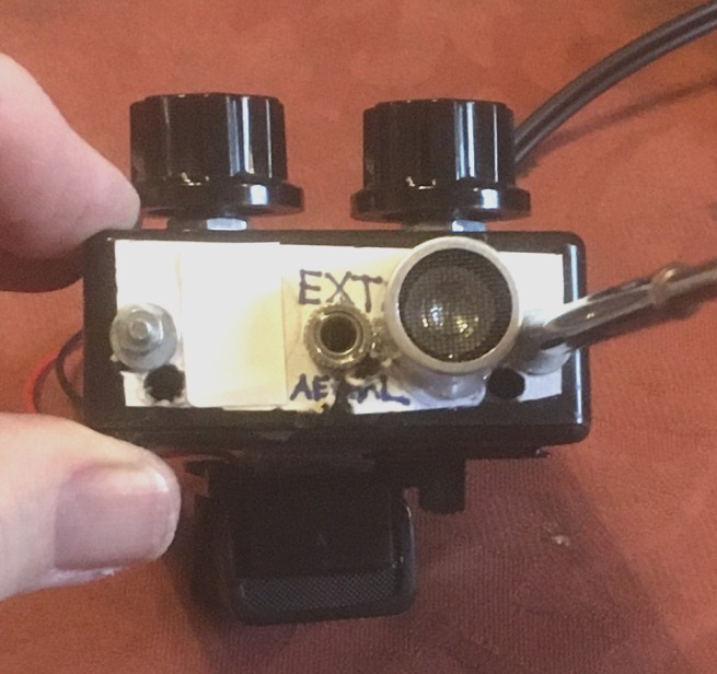
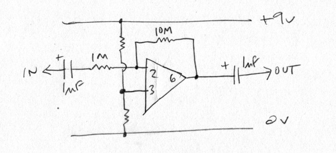
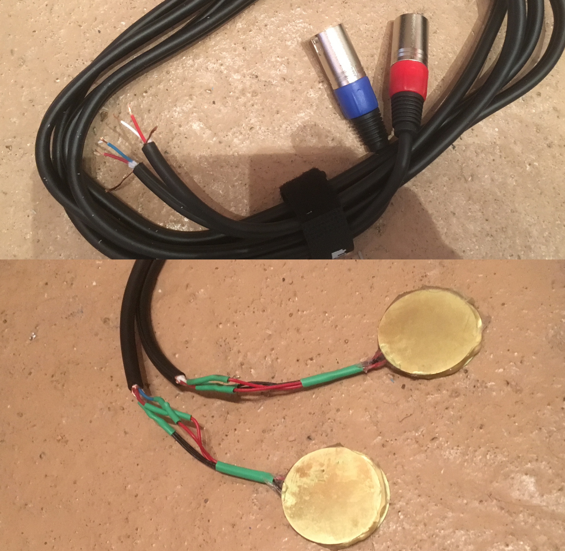
To record the musical box, I used double-sided sticky tape and some piezo contact mics I had made some time ago (as described here).

Here are the two pieces, first the ‘ANDYM’ piece, then the previously composed one (which is called ‘Theme From an Imaginary Spy Film’).

*

Finally, to keep everything together, I used one of the wooden boxes I originally bought at the time I was making the Inductor instrument.  This time, as well as adding the same type of carying handle, I stained it a dark colour and varnished it.  It was a very cheap and rather poor-quality varnish, but didn’t look too bad after a quick polish:

and the musical box, the card strips and everything fitted nicely inside:

18
Mar
20

Parabolic Reflector Microphone 2

After creating my first parabolic microphone system (described in this post), I came across a small commercial device which I thought might be worth trying.  It was hard to say if it was really just a toy, but it looked a bit above that, and had some features that made me think it could be of practical use.

This is the box it came in:

and these are the contents of the box.  Clockwise, we see the approximately 20cm parabolic dish, a pair of decent over-ear headphones, the body of the device, and the quite thorough Instruction Manual:

And, when put together, this is what it looks like.  You can see the revolver-style handle; the ‘trigger’ which turns the microphone on; and the two buttons which record and play back the sound picked up by the microphone, which is in the end of the enclosure on the right,  pointing back into the dish.  Along the top is a x8 magnifier, designed, according to the instruction manual, to allow you to see more clearly what is being recorded.  In the base of the handle is a space for a 9v PP3 battery:

It’s not necessary – or, from my point of view, useful – to use the device’s own recording ability, which is only a 12 second burst.  However, you can also see a 3.5mm output socket in the bottom centre of the device.  This can be used with the headphones supplied, to monitor recordings as they’re being made, or to transfer a recording to a computer or external recorder.  More importantly, it can be connected to an external recorder, while the device is activated, allowing recordings of any length to be made.  Monitoring can be done via the external recorder’s system.

I decided to take the device apart and make a few small changes.  There were three reasons for this.  First of all, I wanted to add an option to replace the internal battery with an external socket, as with the other preamps I use while recording; secondly, I wanted to replace the momentary ‘trigger’ switch with a slide switch, which wouldn’t need to be held down all the time I was recording; and thirdly, I needed to replace the knob on the ‘Frequency Controller’ potentiometer – some kind of filter, I presumed, which was designed, according to the instruction manual, to remove unwanted background noises.  This knob was very stiff and well-nigh impossible to turn, not because of the potentiometer itself, but the design of the knob.

So, I decided to open up the device and look inside.  This involved removing half a dozen screws on the opposite side from that pictured above.  The device seemed solidly contructed, and the plastic had a nice feel to it, like a high quality game controller.  This picture shows what was inside.

1 = The small electret microphone element; 2 = the main circuit board with the large record/playback i.c. and the Frequency Controller potentiometer; 3 the switch board with contacts operated by the trigger mechanism; and 4 = the PP3 battery compartment and clip.

The only place which was still firmly connected was the microphone enclosure.  To get the two halves of the body apart I had to saw carefully through the enclosure at the point shown by the arrow.

Fully opened up, this is what the device looked like:

A closer view of the circuit board shows, in the bottom right-hand corner, the two connections, ‘SWITCH’ and ‘GND’ (Ground, or 0v), which I needed to get at.

This view of the other side of the board shows, in the top right-hand corner, where I made connections.  1 = The two switch wires, which went to a new slide switch attached to the upper part of the handle, within easy reach of my thumb; 2 = The ground connection, which went to a new 3.5mm power input socket further up the body of the device, via an LED, which I added to indicate when the device was activated.

In the bottom left-hand corner you can see the ‘Record’ and ‘Play’ buttons, and the LED which indicates when the device is recording to its internal recorder.

I cut the +9v lead from the battery clip to the circuit board and connected both ends to the LED and a new 3.5mm power in socket.  This was a switched type, so that the device would use an internal PP3 battery, unless a plug was inserted in the socket, in which case the internal battery would be disconnected and power would be taken from an external source.  I attached a small square of black velcro to the outside of the device, close to the socket, for this purpose, as I had done on my other recording preamps.

This picture shows the 3 changes I made to the device.  From front to back you can see: the ‘Record’ switch (recording to my external machine, that is, not the device’s internal chip) and indicator LED; the new, easier-to-use Frequency Controller knob; and the 9v external power socket.

As seen in the previous picture, one of my PP3 battery assemblies with integral 3.5mm plug is fixed to the velcro on the side of the device:

These changes should make the device more practical for me to use.  At some time, when circumstances are more favourable, I’ll try it out in the field.

Edit: I recently had a chance to do that, and it turned out well!  The recordings were reasonably noise-free and you hear, as I move through 360 degrees, a certain amount of directionality as the recorded sound changes.

09
Feb
20

Inductor Pickups 3 – a new instrument

In the first post in this series, I described experiments with different types of inductor pickups.  At the end of this, I had 3 types of pickup which I thought would be of further use: a mono guitar pickup; a stereo pickup using the insides of two Telephone Pickup Coils; and a stereo pickup using two 100mH inductors:

Later I added a similar pickup with two 200mH inductors I had been able to get hold of.

As can be heard in that earlier post, I had used my Macbook as the sound source, but I thought a better one would be a hard drive.

Some time ago I had bought a job lot of broken hard drives from eBay at a cost of about 50p each.  My original idea for these was to scavenge parts from them – magnets, discs, etc. – and to use the arms for a purpose which I may yet get the chance to write about.  (See this post for a description of how to dismantle them).

In this instance, however, I was looking for drives which would power up – many of them didn’t – and might emit interesting noises.  Not noises you could hear directly, but noises that could be picked up by an inductor.

I went through most of the drives – of which the above picture shows just one boxful – and tested them with the 3 inductors I had used in my last test on my laptop: the standard guitar pickup; the two Telephone Pickup Coils; and the two 100mH inductors.  The playing technique was simply a matter of powering up the drive and then passing the pickup slowly over the surface.

Surprisingly, the three different systems didn’t pick up exactly the same noises, and the range of sounds detected seemed sufficiently varied to make an instrument based on this approach worthwhile.  This recording is of the drive pictured, using the three pickups described above, in the order in which they are mentioned, the guitar pickup, Telephone Pickup Coils, and 100mH inductors:

*

It would have been perfectly possible just to use the hard drives spread out on the table, but I decided it would be much neater to make a proper instrument in a box, with its own power supply and preamp.  I was lucky enough to come across a supply of cheap wooden boxes which would be ideal for this project and, hopefully, some future ones.

There would be plenty of room inside for the power supply, circuitry and hard drives.

The first thing I added was an inexpensive handle to the outside (secured with nuts, bolts and washers, rather than screws, to ensure it won’t come off):

The second thing was to install a power source for the hard drives and circuitry.  The obvious thing to do was to use a typical hard drive power source, which would typically provide 12v and 5v DC – the 3.5″ drives would need 12v to spin the discs; 5v would be a suitable voltage for 2.5″ drives and for the electronic circuitry.  These were the main items I bought:

The 240v adaptor fitted into the corner of the box like this:

and an on/off switch was included inside the box lid:

Unfortunately, the mains power supply was too noisy to be used for the electronic circuits, so I used the mains adaptor for powering the hard drives and a PP3 battery for the electronics.

I used a box-type battery holder as it had an integral on/off switch and I was able to glue it securely to the inside of the instrument’s wooden case.

*

So far, so good; but for some reason the hard drives weren’t performing the way they were doing when I had been experimenting with them, and sometimes didn’t even appear to be powering up.  Only when the power supply exploded one day with a loud crack and the lights went off did the penny finally drop! . . .

. . . I went away and researched the amount of power required by a hard drive – and it’s much, much more than I imagined.  The ratings are normally found on the drive itself: the ones I had been using, when I finally read the labels, were rated up to 720mA @ 5v and up to 900mA @ 12v, although often somewhat less, but averaging out at about an amp/amp and a half.  Here’s a couple of examples of where you can find this information on a typical drive:

As you can see, there are big differences between the ratings for these two drives – and even the 5v consumption can be surprisingly high.   And that’s in normal use: when powering up, they can easily consume over 2A each during the first 2 or 3 seconds – no wonder my poor power supply couldn’t cope!  You can see from the label that it’s only rated at 2A at a time for each voltage, so is really only suitable for a single drive.

So, my first step was to buy two new power supplies, 5v and 12v, each rated at 8A – a bit of an expense I wasn’t expecting (about £8 – £9 per device)!   These were no longer to be incorporated into the box; they would be external, connected via two typical centre-positive power sockets on the rear of the box.

I was aiming to incorporate 5-6 hard drives in the box, so the two supplies would provide sufficient power for normal operaration – especially given that there would be no data input or output from the drives – but I had to arrange the power switches so that no more than 2 or 3 of the drives would come on at once.

I could have done this with just a row of power switches, of course; but a more interesting method was to purchase 4 of these ‘delay relays’ at only just over £1 each:

The large blue component is the relay.  It’s not completely in focus in this image, but you can just about see that it can handle 10A (10A of mains voltage, in fact), so was well up to the job in hand.

Item 1 in the above picture is a multi-turn preset, which allowed me to set the delay so the relay wouldn’t come on for at least 2 or 3 seconds – the length of time a high-amperage spike might be caused by a hard drive powering up.  This particular device could be adjusted for a delay of up to 10 seconds, so I set the 4 devices to work as follows:

When the on switch is operated, 12v and 5v power is immediately passed to the first one or two hard drives; after 3 or 4 seconds, power is passed to one or two more drives; and after 6-8 seconds to the one or two final drives.  In this way, overlapping spikes are avoided, and sufficient power is available for the drives to work properly after they are fully powered up.

A series of 6 LEDs, 3 for 12v, 3 for 5v, showed when the power connections were made.

Item 2 in the above picture is where the power lines are connected.  The centre connection is the ‘in’ or ‘common’ connection; either side of this are ‘normally open’ (normally disconnected) or ‘normally closed’ (normally connected) connections, which are then reversed by the operation of the relay.  I needed the normally open connections, so in two devices the centre connection was a 12v line, and in two the centre connection was a 5v line; the normally open connections were connected to the LEDs and the hard drives’ power connectors.

The 4-pin Molex connectors taking power to the drives are wired like this:

Pin 1 (yellow) = 12v;  Pin 2 (black) = Ground; Pin 3 (black) = Ground; Pin 4 (red) = 5v

So, the power section now looked like this (note: the on/off switch wasn’t quite in place when I took this picture):

For a short clip of the startup procedure, click here.

In this test I only used one hard drive connected to each of the three sections – the third one being unusually noisy!  They are, of course, all broken in some way, but you can hear that the first two, as they start up one by one, are not at all as rattly; but these are not the sounds the instrument is designed to create: as we will hear later, each drive creates its own interesting sounds when probed by the instrument’s inductors.

*

So much for the power connections.  Next, the electronics.

The first part of the circuitry was a preamp for the inductors.  For this I used the same transistor-based preamp I had used before for electrets and inductors, with the inductor connected on the left where the microphone is shown:

As this was a stereo instrument, with two inductors fitted side-by-side, as shown above, I used two of these preamps.

*

I tested this, and it worked fine with the mains adaptors for the hard drives and the battery for the preamp, so I turned next to adding a tone control.  I thought, as the instrument was based on inductors, that an inductor-based tone control would be the ideal thing, similar to the design that I had made before in the Bits & Pieces series, the ‘Active’ Tone Control  – which, in reality, is a passive tone control with a x10 amplifier in front of it to counteract the drastic loss of signal strength.

This is my design for the two-channel version:

In this case I used a TL072 instead of the 741 in the original: it was more up-to-date, less noisy, and neater, having two op-amps in one single 8-pin package; I also altered the resistors between the inputs and outputs (pins 2 and 1, and pins 6 and 7) from 100k to 1M to further increase the amplification.

The only thing I found is that I sourced the parts for the original about 20 or 30 years ago, when it was evidently much easier to obtain a 1H inductor – this is a very large value, rarely seen nowadays, and I couldn’t find one.

However, inductors are like resistors, you can put them in series to obtain larger values, so I bought 10 @ 200mH, which only cost about £1, enabling me to create two inductors of 1H.  I spaced them out on the circuit board, hoping to minimise interaction between them, and connected the outputs of the preamps directly, without a switch.  This tone control varies the sound quite a bit over its full range, and I was fairly sure there would be one position which would be very similar to the unaltered sound of the inductors picking up the sounds of the hard drive in action.

(In the event, I had a problem with the circuit around the TL072, so the amplifier and the tone control parts of the circuit ended up on separate boards, as can be seen in later pictures).

The 8-way phono socket panel in the bottom left is where the pairs of inductors plug in, and allows 4 separate pairs to be connected at the same time.  Multiple Molex power connectors like the ones illustrated above allow a number of different drives to be running at the same time, giving the possibility of more complex, multi-layered sounds.

*

The following picture shows the electronics in a more or less finished state in the lid of the box:

On the left, from top to bottom are Panel 1: 9v Battery Power on indicator light, 3.5mm stereo audio out socket, Tone and Volume controls;

Panel 2: 4 x Stereo Inductor inputs;

Panel 3: An LED on the left for 12v power on, and an LED on the right for 5v power on – the third hard drive or pair of drives.

On the right, from top to bottom, are the circuit boards for the tone control, the transistor-based buffer/pre-amp, and the op-amp-based pre-amp; and at the bottom, the 9v battery box with integral on/off switch.

*

To finish the instrument off, I just needed to arrange for the hard drives to be secured in the main part of the box.

I began by putting in a layer of foam rubber, mainly with a view to deadening the sound of the spinning drives.  Some time ago I had purchased a roll of foam, advertised as a yoga mat or sleeping mat.  It only cost about £4.50 and was quite big – about 2 metres by half a metre (perhaps rather narrow for sleeping!), and seemed the ideal thing for this purpose.  I lined the box with the foam, sticking it down with hot glue.  (Again, this is before I replaced the power supply).

To keep the hard drives in place, I used blocks of polystyrene, and cut more squares of foam to insulate drives which would have to sit on top of others.

Cutting polystyrene is messy and rarely successful, so I used an electric polystyrene cutting kit with a heated blade, like the one shown below.  This cost under £10 and proved considerably easier and neater in this and other projects – and elsewhere in the house.

Taking care not to set light to anything, or breathe in fumes from burning polystyrene, I trimmed the pieces without causing any mess.

Turning to the case, I decided a companion box was needed to transport the leads, power supplies and spare hard drives; so I fixed another of the carrying handles to the new box, and stuck on two small engraved plates to indicate which one was the instrument and which one carried the parts.

Using the two boxes, the instrument and accessories could easily be transported together.

A small length of yellow plastic from a cable tie was fixed to the right-hand side of the lid of the instrument box to ensure that it stayed open at the best angle.

I recorded the instrument using Audacity on one of my old MacBooks.  The pair of 100mH inductors were very noisy.  I didn’t have time to find out why, so I unplugged them; but I found that the most productive technique was to use two sets of inductors – the 200mH and the telephone coils – one in each hand.  This enabled me to search for interesting sounds in two places at once, to balance these sounds, and also on occasion to create interactions between them.

It was also possible to lay one set carefully on a drive, to continue picking up sounds, and leaving one hand free to operate the tone crontrol.

The following sound file illustrates some of the typical electrical/mechanical/drone sounds I was able to get from the drives:

20
Jan
20

Electret microphones and a parabolic reflector

One final – well, maybe not final, we’ll see how it goes! – type of microphone I wanted to try while out field recording was a parabolic dish or reflector.  I planned to use electret microphones in the way described in the series of articles beginning here.

Strictly speaking, the three-dimensional shape of the parabolic reflector is called a paraboloid, and the adjective is paraboloidal. A parabola is the two-dimensional shape and the distinction between this and a parabaloid is like that between a sphere and a circle, according to the Wikipedia.  However, in informal language, the word parabola and its associated adjective parabolic are usually used in place of paraboloid and paraboloidal.

So, this is the shape of the dish.  Note that there is a point marked ‘focus’.

Diagram by Melikamp – Own work, CC BY-SA 3.0,
https://commons.wikimedia.org/w/index.php?curid=28181019

So, now we know exactly what we’re talking about!

*

As with some of my other recent experiments, it’s not so much the microphone itself as the way it’s mounted that’s significant; and the significance of the particular shape of the parabolic dish is that all the sound captured within it is reflected back and focused on a single point a few centimetres from the centre of the dish. The effect of this is to naturally amplify the sound captured – and amplify it by quite a lot.

This diagram illustrated how the sounds coming into the dish are all focused on the same spot – the spot where the microphone is placed, facing back into the dish.

Own work assumed (based on copyright claims)., Public Domain,
https://commons.wikimedia.org/w/index.php?curid=3222214

In addition to this, the captured sound is from a restricted area, directly in front of the dish, so what it allows you to do is pick out an individual sound source – a person, bird or animal, machine or natural feature – some distance away and record it without having to get too close, which may cause disturbance, or resort to extreme amplification, which may cause noise or instability.

This is basically the audio equivalent of using a telescope – and, indeed, astronomical telescopes – not just optical, but also radio – use parabolic reflectors to focus light or electromagnetic waves, as do satellite TV dishes.

This photograph from the Wikipedia, showing the receiver from the MERLIN array at the Mullard Radio Astronomy Observatory, Cambridgeshire, is essentially a giant version of the parabolic reflector microphone, and illustrates the reflector’s features: the shape of the dish and the focus point – usually in the centre (although typically on the edge of a TV satellite dish).

Photograph y Cmglee – Own work, CC BY-SA 3.0,
https://commons.wikimedia.org/w/index.php?curid=33433585

The idea of using a parabolic reflector to gather sound from a distance has been going for a long time – since classical antiquity, in fact, as the Wikipedia points out, when the mathematician Diocles described them in his book On Burning Mirrors, and it has been claimed (although probably wrongly) that Archimedes used parabolic reflectors to set the Roman fleet alight during the Siege of Syracuse in 213–212 BCE.

In the UK, as far back as the First World War, giant concrete ‘sound mirrors’ were erected on the south and east coasts. Before the invention of radar, using these structures to listen for the sound of their engines was the most effective way of detecting the approach of enemy aircraft.

The caption to the above photograph – also from the Wikipedia – says: ‘On the pipe in front of the acoustic mirror was a trumpet-shaped ‘collector head’, a microphone which could pick up the reflected engine sound of Zeppelins approaching from the sea. Wires passed down the pipe to a listener seated in a trench nearby with a stethoscope headset, who would try to determine the distance and bearing of any enemy airships.’

[Photograph by Paul Glazzard, CC BY-SA 2.0, https://commons.wikimedia.org/w/index.php?curid=1667862 – ‘WW1 Acoustic Mirror, Kilnsea, East Riding of Yorkshire, England. Rare 4.5 metre high concrete structure near Kilnsea Grange, northwest of Godwin Battery, a relic of the First World War.’]

This photograph from the same source shows 3 ‘Listening Ears’ together, near Greatstone-on-Sea, Kent.

[RAF Denge photograph by Paul Russon, CC BY-SA 2.0,
https://commons.wikimedia.org/w/index.php?curid=1511357]

A great collection of photographs of a whole range of these sound mirrors from Selsey to Sunderland by Joe Pettet-Smith is featured on this page from the BBC website.

Concrete Blocks

*

Normally, commercial parabolic microphones are extremely expensive, although excellent ones are available from companies such as Telinga and Wildtronics.

As usual, I tried to do things on a budget, but finding a suitable parabolic dish proved difficult – bearing in mind that the parabolic shape itself is the important thing, as explained above, and a plastic bowl of some other type wouldn’t work as well.

Other factors included size and weight. The reason for the large size of the coastal ‘sound mirrors’ was not just the aim of collecting sound over a large distance; the size of the dish also determines how easy it is to detect low-frequency sounds. In the case of the sound mirrors, the low frequencies of aircraft and airship engines were a priority. This also has to be borne in mind with the portable reflector, which will inevitably be more suited to higher frequency sounds.  This partly explains its popularity amongst those who go out to record birdsong.

As far as weight is concerned, you have to take into account that the dish might have to be carried for quite a while in the field. Wildtronics, in particular, make a point of stating the weights of their dishes, to the extent of naming their thinnest variety Feather Light, and emphasising that it can be folded or even rolled for transportation. There’s heaps of information online about satellite TV dishes – and you’d think a second hand one of these would be a good bet, cost-wise – but nothing about how much they weigh.  However, they look heavy to me, and their particular design style, with the focus point well outside the rim of the dish, makes it seems as if they’d be difficult to wind-proof.

At the other end of the scale, I almost went for this hand-held item below.  However, although it’s much bigger than it looks – some 25cm (10″) diameter – and despite more positive than negative reviews on Amazon, it really did seem a little too expensive (around £25) and a little too small to me, and would almost certainly not be that effective – I’m looking out for a cheaper second-hand one on eBay to give it a try, though!

[Edit: I recently managed to get hold of one for only just over £20, and made a few modifications to it to make it a practical device to use.  I’ve written it up here]

So, in the end, I went with a UK firm I found, who make a decent reflector at a very reasonable price – OK, more expensive than most of my other projects, but reasonable indeed in the world of commercial parabolics. This was Innercore; or Parabolic Microphone, who make a 50cm ABS plastic reflector for about £65 with an integral stem for microphone mounting, a rubberized hand grip and a standard tripod mounting thread. I also bought their spandex wind shield for an extra £10, as I know from experience that wind can be a real destroyer of decent recordings in the field. As the dish is white, a black cover would, in any case, be a good thing from the point of view of concealing the dish – avoiding disturbing wildlife, and so on.

*

When the dish arrived, it was exactly as described, and, as well as the windshield, even included a microphone, User Guide and cable ties to attach the microphone to the central stem.

The central stem had the focal point clearly marked.  As the picture shows, a handle was attached on the back.  The dish, made of ABS plastic, as I said, was surprisingly light and could comfortably be carried for some time; but in the base of the handle is a hole with a standard 1/4″ thread in it, which would fit a photographic tripod.  I have a couple of handheld devices with 1/4″ threads on the top, capable of folding into a small tripod, which could prove useful.

I also acquired a light, but full-sized tripod, which could be used in the same way.

*

The main task, however, was to attach the microphone inside the dish – or, in this case, microphones, as I wanted something of a stereo effect.

This was unlikely to be pronounced, as the only sound entering the microphones would be that captured by the dish.  I have seen 3-microphone systems where two of them are forward-facing, recording ambient sound in Left/Right stereo and one is facing into the dish, recording the sound on which the disc is focused; but I decided to go with my standard 2-microphone set-up and not worry too much about creating mixers for extra microphones or how different the left and right recordings were.

So, to this end, I used a standard twin-phono socket lead, cut the plugs off one end, drilled a suitable diameter hole in the dish, threaded it through and soldered two small electret capsules to the end.

I wanted some small ones, and the only ones I had left after the two binaural projects, – the dummy head and the dummy ears – were a type called WM-61A.  The Panasonic WM-61A was a very popular and often-used quality electret, now no longer manufactured and consequently becoming more expensive; these were not advertised as ‘Panasonic’, and were not expensive, so their quality was not guaranteed . . .

To fix them to the central stem I used an old Allen key and a jubilee clip – the Allen key only because it had a right-angle shape with some straight sides, and would therefore fix fairly solidly in place. You can also see in this picture the blue band which marks the focal point of the parabolic dish.

I attached the lead and capsules to the stem, close to the focal point marker, with cable ties.

The small felt pad on the end of the stem was to protect the wind shield, which was quite thin, and, I thought, could be damaged by the pointed stem.

The final thing to be done was a little wind-proofing.  Firstly, I took a spare microphone windshield, cut a small hole in the end, and pulled it over the Allen key mount, covering the two capsules.

Finally, I pulled the spandex cover over the front of the dish, covering the whiteness of the plastic as well as helping to keep wind out of the dish.

The parabolic reflector was now ready for testing.

I went to a local nature reserve and made recordings in different areas: woodlands, a river path and a small lake with wildfowl.  The following extracts are typical of the results.  The first recording illustrates the difference in what is picked up when the dish is turned in a different direction.

By and large, though, I had to turn the recording levels up too high, and there was too much noise.  The first and third recordings are just as they came out; the second and fourth are the same recordings with noise reduction applied.

The noise reduction makes them just about acceptable to use, but this is contrary to the purpose of the reflector disc, which is supposed to amplify the sound naturally, without the need for noise-making electronics.

So I’m going to have to do more research and find out the cause of this: are the electret capsules at fault?  Are they badly placed within the dish?  Are the sounds I’m trying to capture too faint?  I’ll report back on any improvements I manage to make.

Edit: I recently tested the dish out again in my back garden, and was much more pleased with the results.  I think I was too ambitious the first time out, and trying to capture sounds that were just too far away, turning up the preramp gain beyond what was reasonable.

In the following recording you can hear just a little directionality as I move through 360 degrees:

27
Nov
19

Binaural Recording, Pt 3

After my second experiment in binaural recording, described in Part 2 of this series, the third area of my research focused on the importance of the ears, rather than the head, to the quality of the recorded sound.  The pdf article I had orginally read on the subject had stressed the importance of the shape of ears, rather than the presence of the head, and at least one range of well-known commercial binaural microphones, the 3dio, consists of ears without a head.

So, I set about sourcing a pair of realistic ears.  Some of these can be prohibitively expensive, but I found a type that were more reasonably-priced (a little under £6 for the pair, from China), moulded in silicone, and intended for acupuncture, it said, or medical study.

When they arrived I was surprised, as they were heavier, softer and more flexible than I was expecting – nothing like the hard, fixed ears of the dummy head.  Much more realistic, and softer even than real human ears.

Unfortunately, as you can see here, the right one – on the left in the picture – had been rather crushed in the post, with the ear lobe bent right over:

The insides of the plastic bags seemed quite moist, so I was hoping that if I pulled the ear lobe back and stored the ear upside down, with a bit of weight on it, it would still be malleable enough to return to something like its original shape.  Perhaps when taken out of the bags, the ears would then harden up in the right shape.

In the  end I had to use a dab of hot glue to pin the ear back to its proper place.  The ears became less moist, but not really less floppy after being out of their bags for a few days.

*

The next part of the plan was a pair of ear muffs, readily available from Chinese sources on eBay at about £1.  They come in all sorts of colours and finishes, but the ones I picked on had a fur interior and a faux-leather finish on the outside:

The reason I chose this type was that the fur would provide a certain amount of sound deadening, and the faux-leather would take hot glue.

More hot glue?  The glue, of course, was needed to attach the silicone ears to the ear muffs!

The purpose of this was to be able to use the ears in different contexts, either attached to a dummy head, or used on their own, relying on the ear-shape for the binaural effect, rather than the whole head.

Accordingly, I first obtained a cheap polystyrene dummy head and inserted some long nails to act as a support for the ear muffs:

It took a few tries to get the exact locations for the nails, but I fairly soon had them in the right place to hold the ears at the correct angle:

I then cut a small block of polystyrene to a suitable size to fit the ears on as a free-standing unit.  I estimated that 14-15cm would be a suitable separation distance for the two ears and trimmed the polystyrene accordingly:

The final and most important stage was to add the electret capsules inside the ears and attach a twin phono lead for the output to the preamplifier.

I used smaller capsules than the ones I had used in the dummy head, as it was difficult to make holes in the silicon ears.  In the end I used my polystyrene cutter, which has a small heated blade, inserted the cable between the silicon block and the ear muff backing, attached the capsules and then pushed them down into the ear canal towards where the ear drum would be.

These photographs illustrate this process:

You can also see a certain amount of melted silicone debris, which I had to remove.

After tidying this up and testing the sound was OK, I superglued the cables along the back of the ear muffs to keep the microphones from moving, and the project was finished.  As soon as there is some better weather, I’ll be able to go out and test the three different binaural systems together.

24
Nov
19

Ultrasonic Field Recording

I had been looking for ways of recording sound from scenes which was not immediately obvious.  I had developed an inductor-based recording device which could pick up electrical noise, and the next area I wanted to explore was ultrasonic sound – that is, sounds which are too high for our ears to hear.

A recording of sounds which are too high for our ears to hear, of course, would not be too interesting – you wouldn’t be able to hear anything on the recording, either; but I got the idea of what to do with them from a type of device available commercially in finished or even kit form – a Bat Detector.

Bats make noises which are mostly ultrasonic – too high for our ears to hear – when they hunt and communicate.  What the classic bat detector does is pick up these ultrasonic sounds, amplify them and lower their pitch by an octave or two, so we can hear them.

But not only bats make noises in the ultrasonic region, many noises around us contain ultrasonic elements which we can’t hear as well as elements which we can hear.  Lowering the pitch of the ultrasonic elements would enable us to appreciate the fullness of sounds which at the moment we only hear part of.

There are several ways of changing the pitch of ultrasonic sounds, and there are many circuits available on the internet utilising these methods for producing a bat detector.  The three main ways are:

1. Frequency Division, in which the very high-pitched bat sounds are converted into square waves which can be digitally divided by – typically – 10, to produce a much lower sound, within the range of human hearing. For example, a bat making calls at 50kHz, when divided by 10, will sound at 5kHz – quite high, but well within our normal hearing range of 20Kz to 20kHz.

2. Time Expansion, where sounds are recorded digitally in the bat detector at a high sampling rate, then played back at a slower rate.  This is a common method of pitch-changing in the world of digital sampling (and the method I used in the computer-based Black Widow sample manipulator).

3. Heterodyne, which works on the same principle as the electronic musical instrument, the Theremin: the high-pitched sounds are mixed with equally high-pitched sounds produced by an oscillator inside the bat detector. The aim is to tune the bat detector to produce a slightly different pitch to the bat, as the output is designed to be at a frequency which is the difference between the two pitches. In this case, if the bat is making calls at 50kHz, for example, and the bat detector is tuned to 45Hz, sounds will again be heard at 5kHz.

This latter turned out to be the method I used – in fact, I bought a bat detector kit.  The best commercially available bat detectors are very expensive, providing a wide frequency range to work within, and often providing more than one way to hear the bats.  I should make it clear at this point that I wasn’t particularly focusing on bats – I wanted to listen to any ultrasonic sounds that might be in the vicinity; but I wanted as wide a variety of sounds as possible to be detected and brought into hearing range.

So I found a neat-looking and very reasonably-priced kit, the Franzis Bat Detector, which was available from a number of sources, all at around £20-£25.  It comes in an attractive and quite sturdy cardboard box, which can serve as the container for the circuit when made up, with art work for the two potentiometers required – for frequency and volume – and holes behind which the speaker is attached.

Inside the box is a very small PCB, no more than 3″ long, already populated with about 25 tiny SMD (Surface Mount Device) components:

Together with the board is a plastic bag containing a handful of non-SMD components, which you solder in place yourself.  These include a battery clip (not shown), a 5v voltage regulator, a few capacitors, an LM386 i.c. amplifier, the two potentiometers and an ultrasonic receiver – in appearance rather like a large electret microphone capsule.

Together with the components, there was a nicely-produced and informative booklet, containing general information about bat detection, an explanation of how the circuit works, a circuit diagram and comprehensive instructions for assembly and testing.

*

Beginning at the front end of the circuit, there are many different types of ultrasonic receiver available, and the majority are rather expensive.  The one that came with the kit is the most popular of the more reasonably-priced ones, but is designed to work best at 40kHz, with quite a narrow band of frequencies in which it works at its greatest efficiency.  This is because it is designed to work in precisely that way, usually being paired with an identical-looking 40kHz ultrasonic transmitter, and commonly used together in detection or distance measuring applications.  I was concerned that this frequency restriction might limit the sounds the detector was able to pick up, bats or otherwise, but there is a certain amount of pickup outside the intended operating range.

*

This particular circuit would probably not suit it, but a possible alternative to the ultrasonic receiver in some circumstances would – surprisingly – be an electret capsule.  Although these are sold for use in ordinary microphones, some have good ultrasonic capabilities.  It’s hard to know which ones, and to what extent they might be useful in this regard, as figures are not normally released for frequencies above 20kHz, the normal extent of human hearing.

However, one capsule known to have a good response even in the environs of 100kHz is the Panasonic WM-61A, one which has been tested and used in this way.  Unfortunately, this particular capsule was discontinued more than a decade ago, and remaining ones are getting more and more expensive, even if they can be found.  Some are still advertised on, for example eBay, but I was put off by warnings of possible fakes, whose frequency response would not necessarily be the same.

A good currently available alternative is the Primo EM258 from FEL Communications.  At over £5 each, these were 20 times as expensive as the unbranded electret capsules I’d bought before for other more conventional microphone projects, but they are not much more expensive than genuine Panasonic WM-61As these days, and have been tested and shown to have a good ultrasonic response (better, in fact than the Panasonics, according to FEL).

JLI Electronics manufacture the JLI-61A, which is intended as a direct replacement for the WM-61A, but it wasn’t clear that this was available at a reasonable price in the UK.  In the US this would be a good  alternative, at half the price of the Primo.

FEL, incidentally, also advertise a potentially excellent alternative, a tiny SMD-style MEMS microphone.  Normally these things are practically invisible to the naked eye, but FEL have installed one on a breakout board like this:

The microphone itself is a Knowles SPU0410LR5H-QB, as the legend on the PCB suggests, with a sensitivity to ultrasonic frequencies up to 200kHz and beyond.  It was almost twice as expensive as the Primo electret, but would, no doubt work very well, and that price, just under £10, is not at all unreasonable compared to current good quality alternatives.

Alternatively, the cheapest way to obtain a second ultrasonic detector – other than ordering direct from China – might be to purchase a module like this:

Its purpose is distance measurement – the device on the left, marked ‘T’, is an ultrasonic transmitter, the one on the right, marked ‘R’ is a receiver.  It would be a few moments work to detach the receiver from the board, and attach it at the beginning of the circuit.

*

As for the construction, I planned to fit the circuit inside one of the small boxes I had previously used for microphone preamps; so I connected the small PCB to sockets in the box for power and audio out – I intended to use headphones instead of the speaker supplied.  I also added an extra socket for a line out from the wiper of the volume control.  Together with an appropriate preamp (for example, the one I use for my contact mics), this would enable me to record the ultrasonic sounds I was picking up.


I attached the ultrasonic detector to the front of the box with hot glue, and attached a pair of 2.5M bolts for the two aerials, which had threaded bases (in the end I only used one aerial).  I also added an extra socket for attaching an external aerial or detector; a plug here would disconnect the internal ones.

The remaining parts of the circuit were: a buffer/amplifier for the ultrasonic detector; a high-frequency oscillator, based on 555 integrated circuit; a mixing/heterodyne circuit, and an audio amplifier, based on an LM386 (the only part of the circuit which uses the full 9v available from the PP3 battery).

*

The difficulties with the first part of the circuit  – the buffer/amplifier – if you were to build it yourself, are to do with size.  The specified transistor for this amplifier, the BC849C, is a tiny, tiny 3-pin SMD device.  I didn’t have a 5p handy – physically the smallest coin currently in use – but I did have a 1p, which is only a little bigger, and a BC849C, and this is how they compared:

It would be quite a task trying to attach wires to this miniscule component – but at least they’ve separated the 3 pins onto separate sides.  I obtained this one just as an example – the actual one used in this circuit was already happily soldered to the PCB by the makers!

*

The mixer section is based on a CD2003 chip, ‘originally developed for radio receivers’, as the kit booklet says, ‘the core of an AM/FM radio with oscillators, mixer stages, intermediate frequency amplifiers and demodulators for the two ranges’.  In this design, only the AM preamp and AM mixer stage are used.  According to the booklet, the i.c. ‘offers a total amplification of 40 dB and a suppression of the input signal of -20 dB. The output of the mixer provides a low pass filter for an additional damping of the input signal.’ – a very handy chip for the task in hand.  It is possible to get hold of these, but they are not nowadays common or cheap – except from China, it appeared.

*

After connecting everything together, I plugged the headphones in and tested the detector out, using the preamp I had constructed for the piezo contact mics.

The device worked well: I detected ultrasonic sounds from jangling a bunch of keys and from rubbing my finger and thumb together – everyday sounds known to have a significant ultrasonic component – and outside in the evening I was pretty sure I detected some genuine bats.

This view of the front of the device shows the two potentiometers which need to be accessed when the device is in use: the tuning control on the left, which adjects the frequency of the internal oscillator and effectively ‘tunes in’ the high frequency noise picked up by the ultrasonic detector; and on the right the volume control.

This view of the back shows, on the left, the unit with the 9v battery attached (with velcro, in my usual way); and on the right, without the battery, but showing the caption for the switch, indicating that either the ultrasonic ‘mic’ or the attached aerial can be selected; a 3.5mm plug in the ‘EXT AERIAL’ socket on the front disconnects the switch, so a different size or kind of aerial can be used.

The following sound file gives examples of some quick recordings I made with the ultrasonic detector.  Unfortunately, it’s now late November – much later than when I first tested the circuit out – so no bats flying around.  Instead, I just went round the house for 10 minutes, picking out a few promising locations.

So, you can hear fingers rubbing together, the laptop, TV set, some unexplained radio-tuning type sounds, a low-energy light-bulb, jingling keys, and water streaming slowly into the sink from a tap. The laptop, TV set, radio-tuning and low-energy light-bulb were recorded with the aerial, the others with the ultrasonic microphone-type detector.

The keys are particularly interesting, and I look forward to trying this on some natural sounds outside – especially bats when they emerge from hibernation next spring.

Top

18
Nov
19

Making music with the BBC Micro:bit, Pt 1

Recently I was lucky enough to be given a BBC Micro:bit as a present.

What is a Micro:bit? – It’s a micro-sized computer, half the size of a credit card, with a row of input and output pins along one edge, Bluetooth capability, a display consisting of 25 LEDs in a a 5×5 pattern, and able to be powered and programmed via USB.  For ultimate simplicity, it can be programmed directly from the website www.microbit.org, via WebUSB using the Chrome web browser.

When it was introduced, its purpose was to ‘encourage children to get actively involved in writing software for computers and building new things‘, rather than being merely consumers of media, and around a million of them were given away to schoolchildren by the BBC.

Once I found out that it was considered suitable for primary school children, I was greatly encouraged that I would be able to write programs for it; and, in fact, there is a particularly straightforward way of doing this (as well as Javascript and a version of the Python programming language): that is, the Microsoft MakeCode system, which involves arranging and sequencing interlocking ‘blocks’.  You still have to have the programmer’s mentality, but without having to remember the precise wording and syntax.

As shown in the pictures above, The Micro:bit has a row of about 20 pins on its bottom edge, which have different digital or analog functions, and 5 of them, in particular, are easily accessed with crocodile clips or 4mm banana plugs.  These are +3v (actually 3.3v) and Ground, and analog pins P0, P1 and P2.  As a matter of fact, these last 3 pins can be operated simply by touching them!  You may have to touch Ground with your other hand to make sure they work, though.

Two tactile switch buttons are also available for incorporation into simple programs, and there is a tactile ‘Reset’ button on the back, which causes the Micro:bit to reboot.

For more complex applications – which can even include operating external devices such as servos – a range of edge connectors is available, which can aid permanent connections or take advantage of the smaller input/output pins.

There seemed to be several different ways in which I could make use of the Micro:bit’s capabilities.  First of all, it can, with a speaker attached directly to one of its analogue pins (typically pin P0), make monophonic square-wave sounds of its own, including playing a number of tunes stored in its own memory; secondly, it can be programmed to output MIDI messages; and thirdly, it can utilise and output data from its onboard detectors, which include light and temperature sensing, a three-dimensional accelerometer, and a compass/magnetic sensor.

I decided to start by using the Micro:bit’s internal sound-generating capabilities.

For this, I decided to make a module into which the Micro:bit could be inserted, and which would contain a power supply, speaker and various input and output sockets – all the hardware needed for a free-standing Micro:bit-controlled musical instrument.  That is the subject of this post.

*

I began with an empty Stylophone case, left over from an earlier project.  I left the speaker in, and the two slide switches on the front left.

In order to incorporate the Micro:bit, I bought a ‘proto-board’ – an edge connector into which the Micro:bit slots at a right-angle, with a section of stripboard attached for ancillary circuits to be built on.  I chose the right-angle one because I needed the Micro:bit to be visible when in use, and to have access to the front and back of the Micro:bit where its sensors are located.

I used this board for a couple of things: a simple op-amp based buffer/voltage follower, and an audio output transformer to be used with an alternative to the speaker, a piezo element.

I also bought a sturdy protective cover for the Micro:bit to ensure that it suffered no damage while being plugged in and out.  This particular type of cover leaves the edge with the pins exposed for just this sort of application.

This picture shows the board in situ, kept in place with matchsticks used as locating pins.  The transformer and op amp are on the right-hand side; on the left are a 4-pin i.c. socket and capacitor left over from an experiment with an audio amplifier, which I decided not to keep.

The voltage follower is the simplest possible op-amp circuit:

I used one half of an NE5532, as that’s what I happened to have available, but any op-amp can perform this task of ensuring the output has a suitably low impedence level.

I’m not sure how useful the transformer is in this exact context, but I learned of its use with piezos from this Nic Collins video on YouTube and had bought a handful of them for this kind of use.

These pictures show how the piezo was fixed into the former Stylophone case, from the inside (L) and outside (R) in the place previously occupied by the tuning knob, which protruded from the bottom of the case.

The Micro:bit can also be powered through thie proto board: mine had a terminal block already installed in it for +3v and Ground; I powered the unit with a PP3 battery, as I am wont to do, so added a small adjustable voltage regulator before the terminal block, set at 3.3v.  This meant that the Micro:bit was receiving its correct voltage, but more volts (up to 9v) would be available for any additional circuitry required.  Two LEDs show whether the 9v and 3.3v parts of the circuit are powered up.

While working on the inputs and outputs, I added the following: an external 9v power in socket; send and return sockets so that external tone controls (such as these) could be used; sockets for an external speaker or headphones and an external piezo; a line out socket for easier mixing or recording; and two sockets connected to analog input pins P1 and P2.

Pin P1 was connected to a 10k lin potentiometer, one end of which was connected to 3.3v, the supply voltage for this part of the circuit, the other to 0v; in this way a continuously variable voltage could be available at pin P1 for control purposes: the Micro:bit would interpret this as a number between 0 and 1023.  If something was plugged into the P1 socket, the potentiometer would be disconnected and the external signal read by the pin instead.

Pin P2 was not connected, unless something was plugged into the P2 socket.  A second 10k lin potentiometer, set up exactly like the one for P1, was added, terminating in a 3.5mm mono plug.  This was available to be plugged into the socket and used for the same purpose if a program were to require it.

In use, I found I had problems with the circuit if the PP3 battery wasn’t new or, if rechargeable, well charged; fortunately, with the external socket it would be possible to use a mains adapter.

*

I set the mIcro:bit up to make some trial tones, but the sound was rather quiet, through both speakers and piezo, so I added a small amplifier.  This was a very economical (99p) module from a UK eBay seller, based on the PAM8403 chip.  This is a 3W stereo amplifier chip, but I would only be needing one of the channels.

It required a 5v supply, so I powered it from the 9v source and added a small 7805 5v regulator.

7805

I put a 10k log volume control before the amplifier input, with the line out socket between the volume control and the amplifier input.  If a plug is inserted in the line out socket, the signal to the amplifier is cut.

After the amplifier there is a 3-way switch to choose between internal speaker, external speaker or headphones, and piezo element.

The following picture shows the majority of the interior at the end of phase 1 of construction (but before I added the two LEDs):

Features marked: 1 = the original Stylophone switch PCB, repurposed for 9v on/off and 3v on/off; 2 = volume control; 3 = the original Stylophone speaker; 4 = the 5v voltage regulator and amplifier PCB; 5 = the 3.3v voltage regulator PCB; and 6 = the 3-way audio output switch (internal speaker/external speaker or headphones/piezo element).

On the exterior I added three tactile switches to replace the two switches A and B on the front of the Micro:bit.  The first two switches simply duplicate the effect of the two switches on the Micro:bit; with the aid of a couple of diodes and a 4066 digital switch i.c., the third tactile duplicates the effect of pressing A and B at the same time, an action recognised by the Micro:bit.

I didn’t add any pull-up resistors on the outputs of the 4066 as the Micro:bit already has these internally.

*

After this I had a working module, so it was time for some programming!

*

I started with a couple of simple programs to make use of the light sensitivity and magnetometer functions.

While experimenting, I connected the Micro:bit to my Macbook with a USB cable, opened the Chrome web browser and wrote the programs using MakeCode on the microbit.org website.

The following picture shows the main features of the coding page:

1 = the simulator.  Most – but not always all – of the coding you write is automatically simulated here.  As you can see, the first instruction of my program, to display the number 1, is shown, as is the indication that I have chosen instructions which require the speaker to be attached;

2 = the button you press to load the program into your USB-connected Micro:bit.  WebUSB has not yet been implemented in most web browsers, which is why I use Chrome to do this.  Incidentally, if you’ve made any syntactical errors in the program, you will be told when you click this button;

3 = the area to name and save your program as a hex file.  The alternative way to program the Micro:bit is to open its window and drag and drop a hex file onto it;

4 = where you choose to program using the blocks, as I have done, or to write the code in Javascript;

5 = the area where the program is written.

*

As for my first program: the light control on the Micro:bit takes advantage of the fact that if the current to an LED is inverted, it becomes (slightly) sensitive to light.   The Micro:bit has an array of 25 LEDs on it, and it’s possible to use 9 of these together to record light levels on and around the device.

I found that the most useful way to use this feature was to set the Micro:bit up to sense the ambient light level, and then react to brighter lights being shone onto the LEDs, rather than the other way round (i.e. reacting to being shaded from the ambient light).

In this case, the reaction I programmed was to sound a note, then increase the pitch of that note as the light level increased.  Initially I just used the torch in my mobile phone, but I had already made 2 devices which could be used to control the Micro:bit in Light Reactive mode, the UFO and the Shuttlecraft.

As I said, the Micro:bit was programmed to start up in a waiting state and display the number ‘1’:

Then, when its Button ‘B’ was pressed – or the Button ‘B’ on the top of my module – it would run the part of the program related to the Light Reactive Instrument and display the number ‘3’:

The Micro:bit outputs a number between 0 and 255 to represent how bright the light level is.  0=dark and 255=bright.  The variable lightlevel in the program is set to be 20 times this number, i.e. between 0 and about 5,000.  The opening pitch chosen, 220Hz (the note A below middle C) and the range of values represented by lightlevel is designed to allow the Micro:bit to output pitches between 220Hz – a low to medium note – and about 5kHz – a very high note.

The variable lightambient is used to sample and remember the normal light level around the instrument on startup.  If the light level is no greater than this, the instrument makes no sound, the idea being that it should remain silent until a light is deliberately shone on it.

*

The second simple instrument I programmed was, in essence, the same thing, but reacting in this case to the presence of a magnet.

The Micro:bit measures magnetic force, as it says above, in microteslas (µT).  It turned out that the range of readings it gave did not need scaling or multiplying like the light level readings did, but produced a useful range of pitches without any changes.  So in this case the variable magforce was equal to the microtesla reading and gave rise to an output at the same Hz as the reading.

In this case, a magnet in the vicinity of the Micro:bit caused a pleasing arpeggiated effect, increasing in pitch the closer the magnet came to the Micro:bit, and decreasing as it was moved further away.

Again, the variable magambient was inserted in order to stop the instrument from sounding until the activating magnet was intentionally brought close to it.

I bought a neodymium (NdFeB) magnet especially for this purpose, as these are particularly powerful – up to 20 times as powerful as conventional ferrite (iron) magnets, in fact.

Neodymium magnets are graded from 28-52 according to their strength.  This one was an N52 (highest power) type.  It works very effectively, but has to be kept well away from any metal parts of the instrument – indeed metal parts of anything – as it will stick very easily and very strongly to them.  I wasn’t sure, but it even seemed to be affecting the speaker in some instances – a speaker, of couse, being driven by a magnet.

The only negative thing about this second instrument is that every time you reboot the Micro:bit, the compass/magnetometer has to be reset if you come to use it.  This is not, unfortunately, a simple matter, as you have to turn the Micro:bit every which way, with your progress shown by the LEDs lighting up one by one.  Only when all 25 of them are lit can you proceed.  This is obviously critical, if you genuinely want an accurate compass direction, but not so critical if all you want to do is make entertaining noises . . .

*

As I mentioned earlier, I had added two potentiometers connected to analog input pins P1 and P2.   I didn’t have an immediate use for these, but I thought it would be handy to have two variable inputs – for tuning or transposition, for example.

In preparation for Phase 2 of the instrument, I made use of the input to pin P1, and programmed it in the following way:

At the beginning of the program the potential input from pin 1, 0 – 1023, is divided into 21 equal sections, and scaled down to 0 – 20.  Each of the 21 divisions is numbered. ‘notenumber 0’, ‘notenumber’ 1′, ‘notenumber 2’, etc.

There are 20 notes on the former Stylophone keyboard, so there is one number for ‘off’, and one number for each note on the keyboard, ranging from 220Hz (‘Low A’) up to 659Hz (‘High E’).  When the potentiometer connected to pin 1 is turned fully anti-clockwise, the instrument is silent; as it is slowly turned clockwise, each note is stepped through in turn, until the highest note, ‘High E’ is reached.

This experiment proved that it should be possible to connect the keyboard to pin 1 and use the Micro:bit like a Stylophone.  This what I intend to do in Part 2 of this series.

Meanwhile, here are some recordings of these two instruments.  There are 8 short recordings, following this pattern: first the Light Reactive instrument through the internal speaker, external speaker, internal piezo element amd external piezo element; then the Magnet Reactive instrument through the same four media.

The recordings with the external piezo, glued to the bottom of the tin, are particularly interesting.  My experiments with piezos (beginning here), have so far only been in using them as microphonic elements, in particular as contact microphones, and as part of custom-made percussion instruments, and although the introductory article refers to their use as speakers, this is the first time I had actually used one that way.  Hopefully, there will be an opportunity to complete my survey of piezos by looking into this in more detail.

The tin, in fact, had been prepared for use as a kind of drum – and could easily function that way if attached to a suitable preamp.  It is quite large in size – 22cm (about 8.5″) in diameter and 14cm (about 5.5″) deep – and would make a very effective drum.  In this instance, using it as a speaker adds a noticeable reverb effect to the sound of the Micro:bit instrument.


17
Aug
19

Binaural Recording, Pt 2

After trying the commercial microphones in Part 1 of this series on Binaural Recording, I thought I should try something more home-made – although this also involved a large-ish initial purchase.

What I bought was this handsome life-size mannequin head, intended for work in a hat shop:

The idea, of course, was to install microphones in the ears of the dummy head.  It was made of a fairly hard, but not too brittle, plastic (PVC, I believe it said in the eBay listing), which seemed to be a couple of millimetres thick.

There were several things I particularly liked about this style of head: first of all, the realistic appearance – the whole point of binaural recording is realism, so the closer the recording device resembled the human head, the better.  Unlike some mannequin heads, however, this one wasn’t painted to look like a real person – that would be too spooky! . . .

In particular, the ear was quite well-fashioned:

A big part of the way we hear things is because of the size and shape of our ears, so the accuracy of the ears of the dummy head would have an effect on the quality of the recordings.  For similar reasons, some dummy heads for recording include shoulders, as sound will bounce off these into the ears.

Finally, the underside of the base had a socket which would make it possible for the head to be mounted on a pole or stand, so as to be set at an appropriate sitting or standing height,  whichever was required for a particular recording situation.

*

My task in this case was essentially to drill suitable holes in the mannequin’s ears, and insert a pair of electret capsules.  I began by soldering a pair of capsules to the cut ends of the twin phono lead I had left after removing 10cm of one end for the previous project.

The capsules were like these:

The lead with the three connections to the side of the capsule is the Ground lead, the other is the signal.  I connected the two capsules this way, with some shrink tubing to make the joints stronger and stop them short-circuiting.

Turning to the mannequin head, the base was only attached by a dab of glue on one side, so came off easily with a little twisting and a cut with a craft knife.

It was a fairly quick procedure to drill 3 holes in the head: one in each ear, slightly smaller than the size of the electret capsules, and another, larger one at the back for the leads to exit from:

I pushed the lead in through the hole in the back, ran a big blob of hot glue round the front edge of the electret capsules and stuck them just behind the ear holes.  I chose hot glue as it’s easy to remove in case the capsules need replacing at some point in the future; it didn’t matter if a bit of the glue came over the front edge of the capsule as the actual hole on the front which the sound goes in through is very small, just a millimetre or so, right in the middle of the capsule.

Looking inside through the base, you can see how the electret capsules are stuck inside the ear, and the cables are held in place with more hot glue:

This took only a matter of minutes, and the final result looked like this:

As you can see, the microphones are held discreetly in the ear holes, and the twin phono lead, which connects to the preamp, exits from the large hole in the back of the neck, where it’s held in place by further hot glue.

*

The cost of this project was £10.50 – about half as much as the first one.  The mannequin head was £9.50; the electret microphone capsules about 25p; and the half phono lead was 75p.

The only other thing to consider is whether the head should be filled – and, if so, what with – to more accurately reflect the fact that human ears are separated by more than air.  The human brain is about three-quarters water and has the consistency of jelly or tofu; it’s quite heavy, but soft and squishy, and you can’t really pick it up until it’s been preserved in some way, which most brains we see pictured have been.

So what the best thing would be to fill the head is difficult to decide, given that jelly or tofu would soon go off.  In one article that I read the dummy head maker installed the microphones then filled the head with liquid silicone, which gradually set solid.  That seemed to be a good plan, although there’d be no way of getting to the microphones again if there were a problem with the capsules or the wiring.  My thinking is it would be sufficient to use something sound deadening, like wool or felt, to ensure that the microphones would only be picking up sound from outside.

[Edit: This is what I did, filling the empty head with a pyjama jacket, which I had been bought but had never worn].

*

In the third part of this series, I’ll complete the final project, do some recording and compare the results.

In the meantime, here’s a short extract from the first recording I made with the head:

17
Aug
19

Binaural Recording, Pt 1

I’d done some field recording with conventional microphones, and after recording with contact microphones and hydrophones, as described in this post, I decided it would be interesting to try binaural recording.

Binaural recording is an attempt to record in as likelike a way as possible.  Since both the size and shape of our ears and the fact that they are placed on opposite sides of our head are important factors in establishing the quality of the sound we naturally hear, binaural recording attempts to replicate this by, most usually, placing microphones within the ears of a dummy head.

‘Lifelike’ aspects which could be captured by binaural or dummy head recording include time differences in the arrival of sounds at one ear or the other, and types of frequency-dependent level differences and distortions which vary with the direction of the sound source.  These would allow a listener using headphones to gain extra information about the precise location and distance of sounds they were listening to; information which would not as readily be apparent if the recordings were made with conventional microphones or played back via loudspeakers.

This article [note: it’s a pdf] refers to three ways in which binaural recordings preserve ‘cues’ as to sounds’ direction and location.  These are, in order of importance: the shape of the ear; the time difference between sounds arriving at one ear, then the other; and, least significantly, it says, the presence of the bulk of the head between the two ears.

(This isn’t a universally-held view: a number of binaural recording devices feature two microphones, side by side, and separated by a sound-absorbing panel.  A notable example of this is the Jecklin disc, which has a diameter of 35cm, is covered with sound-absorbing foam or fleece, and placed between two omnidirectional microphones).

I experimented with three ways of creating binaural recording devices, comparing the results in terms of quality, practicality and cost.  I intended to use the pre-amp I had originally designed for use with electret capsules, and which I had built into a handy case when developing an inductor pickup, so I didn’t include this in the cost.  The pre-amp – which in any case was very cheap and simple – looked like this:

and the case like this:

The preamp is stereo, so inside there are two of the circuits above.  The inputs are phono sockets; the output, a 5-pin XLR, is compatible with the connecting lead of my recording device, a Marantz PMD-660.  The 3.5mm mono socket was for a 9v power source; the velcro on the top of the case was to mount the holder for a PP3 battery.

*

The first, and simplest, method involved purchasing the microphones!  I found that Roland made a very useful-looking pair of microphones resembling ear-buds, the idea being that you would wear them while recording – no need for a dummy head when your own head could do the job!   This set (CS10-EM) sounded as if it would be particularly effective, as the microphone earpieces also contained earphones, enabling recordings to be monitored while being made.  The downside, however, was the cost: over £70 on Amazon – a reasonable price, I suppose, for a potentially very useful pair of microphones, but not in the price-range for projects in this blog.

However, I noticed that Roland also made a similar pair of microphones for use with GoPro cameras, the WPM-10 WearPro:

Although this set didn’t have actual earphones for monitoring, the cost was considerably less: just under £20, including postage; so I invested in a set.  When it arrived, it contained a choice of different-sized earpieces, so it was possible to select the best fit for your ears; and, as can be seen from these drawings, it also included a pair of foam covers that might have an effect – albeit a small one – on pick up of wind noise.  Having fitted them, it didn’t look to me as if they would stay on for very long, though, so I didn’t plan on using them.

Because of their intended purpose, the plug on these microphones is not an audio plug, it’s a mini USB.

Except that it isn’t a simple mini USB plug at all.  A standard sized USB plug has 4 pins; a mini- or micro-USB has 5; this one is the size and shape of a mini-USB, but has 10.  I suppose it could be called a proprietary connector, as a number of manufacturers use them, but not always in the same way.  GoPro uses them like this:

The connections in the row along the bottom are the standard mini- or micro-USB set: +5v, Data-, Data+, ID and Ground.  ‘ID’ is the one omitted from the standard-sized USB connection: using standard-sized USB connections, the ‘in’ socket on a host device (e.g. a laptop) should be the narrow, rectangular one, Type A; the ‘out’ socket on a peripheral device (e.g. a printer) should be the square one, Type B.  With mini- and micro-sized sockets, there is no distinction in shape between these ‘in’ and ‘out’ sockets, so the job of distinguishing them is done by the ‘ID’ pin.  If the socket is performing the job as a peripheral – e.g. a camera, the ID pin is not connected; if as a host, e.g. a laptop, it is connected to Ground.

In the case of the GoPro, the device responds differently to different resistances between the ID pin and Ground.  As shown in the diagram, a resistance of 100k between ID and ground causes the device to function as a video and audio source, and it can be plugged into an external video/audio receiver; a resistance of 330k, and it will receive signals from a microphone.  In both cases, the presence of a resistance between ID and Ground allows the upper 5 pins to come into operation; their specific use is shown in the diagram above.

(I have seen it suggested that a resistance of 33k allows both these functions at the same time, but that was not confirmed by experiment in the article where I read it).

The reason for the resistor shown with a dotted line is that the conventional place to connect the 33k/100k/330k resistor would be the case of the plug, but one experimenter who posted a video on YouTube had difficulty with this, and used the Ground pin in the centre of the upper level instead and confirmed that this worked fine.

*

However, I don’t have a GoPro, and this is not the way I intended to use the microphones – in fact, it was the exact opposite.  What I needed to do was remove the mini-USB plug altogether and attach instead two phono plugs, so that the microphones could be used with the preamp shown above, for recording on my Marantz machine.

I was banking on the fact that these microphones would be a pair of electret capsules, and would receive sufficient power from the preamp to operate correctly.

So, as I had done before, instead of buying a pair of separate in-line phono plugs, I bought a 2m twin phono lead – it was only about £1.50 and would, when chopped in half, make two single-ended twin leads.

I took one of the leads and the WearPro microphones:

and cut off the mini-USB plug from the microphone lead.  As expected, this left two signal leads, Red for right, Yellow for left, and two unenclosed ground connections.

I didn’t need a whole metre of extra cable, and my next project would require as much of the 2m as could be spared; so I cut off one pair of phono leads with about 10cm of cable.  In this case the two signal leads were red and white, and the two grounds were black.

All I had to do was connect these 4 leads together, red to red, yellow to white and black to copper, and test the microphones with my recorder.

The test was fine, the microphone in my left ear was recording to the left channel of the recorder, the microphone in my right ear was recording to the right channel; so I sealed the wiring with shrink tubing and duct tape.

I used duct tape because the quality of the electrical insulating tape I’ve been coming axross recently has been terrible: neither flexible enough or sticky enough.  After I took the lower picture I added an overall layer of duct tape to bind the two wires securely together.

*

The cost of this project was £19.75 – the microphones were £19 and half the phono lead was 75p. Afterwards I felt slightly guilty at being lazy and buying the microphones.  It would have been possible to buy a pair of headphones or earphones and adapt them by gluing electret capsules on the outsides and transferring the wiring from the speakers to the microphones.  The electret capsules would have cost no more than about 20p each, and the price of a pair of not-very-good headphones or earphones would have been minimal, so it could have been done for a quarter or a third of the price.

However, this was a neat solution, took only a few minutes to finish, and the resulting set up looks good.  The quality comparison of my different binaural systems – and sound files – will come later, after I’ve finished all three projects, but this one is going to have the advantage when it comes to practicality, as it’s very simple and discreet, certainly the best solution for situations in which I don’t want to be advertising the fact that I’m recording.

This was my first recording with these microphones. I started in the hallway, walked out of the house into the shed, out of the shed, brushing past some bushes, picked up and started filling the watering can from the water butt, then turned and walked back towards the house. No noise reduction has been applied to the recording, which shows you can get a decent clear sound from the WPM-10s.

As soon as I had completed the project, I took the remaining part of the phono lead and moved on to the next one, which is described in Part 2 of this series, here.

08
Aug
18

Stylophones 6 – The Soviet Stylophone

With the help of a correspondent to my blog I was lucky enough to get hold of an early 80’s ‘Stylophone’ from the Soviet Union.

Entitled the ‘Gamma’, I’m told it was made in the city of Chernivtsi, a part of the Soviet Union now in western Ukraine.

Larger than a Dübreq Stylophone, it came in a neat plastic box measuring about 25x20x5cm.

Inside, the Gamma Stylophone itself has a 20-note keyboard at the front, a stylus – more complicated than a Dübreq Stylophone stylus – on a twin lead, a volume control on the left-hand side, and a speaker in the top left-hand corner.  A coloured label indicates the notes of the scale represented by each section of the keyboard.

There are also 3 strange slots above the keyboard, which are slightly wider than the keyboard and just deep enough to be accessed by the stylus.  This close up of the keyboard shows the middle of two of these slots:

The stylus, as mentioned above, is more complicated than the Dübreq Stylophone stylus in that it includes a combined press and slide switch.  It turned out that the press switch had to be pushed for the stylus to work; the slide switch turned the vibrato on or off.

Helpfully, my correspondent had cleaned the instrument before sending it, so there wasn’t a lot for me to do!  I opened the case – just 4 slot-headed screws underneath – and examined the insides.  The circuit board was attached to 4 mounts on the base; the speaker had 4 mounts on the front.

Turning the circuit board over, I could see the components and the layout.  Everything seemed neat and well made, with a good solid loudspeaker.

The components on the circuit board weren’t quite the same as their Western equivalents, but quite recognisable, nonetheless:

I removed a little more of the disintegrating foam – and replaced a speaker wire, which I had inadvertently detached – and then turned to the power cables.  The battery fittings had been removed, but I could see from the booklet which came with the instrument, that these had been designed for a pair of Soviet-style 4.5v batteries: my correspondent explained to me that these were similar to a group of three 1.5v batteries – not unlike the kind of thing we used to have inside cordless phones – but which were, in any case, now uncommon.

I just added a PP3 battery clip, similar to the type one would find in an old-style Dübreq Stylophone, which worked fine.  I hadn’t intended to ‘circuit-bend’ this device, but I pondered on adding an on/off switch, as there isn’t one in the original design.

I attached the battery and tried it out.  The push switch needed a bit of attention – a few squirts of contact cleaner helped – but all the notes sounded perfectly, and the vibrato turned on and off.  I wasn’t able to check that the notes were in tune, and there’s no fine tuning control, which you would find on a Dübreq Stylophone, but I’ll look into that later.

The booklet that came with the Gamma Stylophone was delightful – the paper and printing quality weren’t high, but the illustrations were beautiful and the colourful instructions on how to play the many songs were attractively set out.

Read the Gamma Stylophone Booklet.

I’m told that Chernivtsi is in the region of Bukovina, which lies partly in the Ukraine and partly in Romania, and that the costume of the dancer in the picture is from this region.

The serial number in the booklet and on the back of the instrument is ‘304’.  It is normal, apparently, for these instruments to have 6-figure serial numbers, so this could be a very early example.

There is no circuit diagram in the booklet, but this is said to be unusual in the Soviet era when it was common for these to be included.

Here’s a short video of me testing the Gamma Stylophone.  You can see from this clip how the stylus switches function – and also what the 3 extra slots are for!

Continue reading ‘Stylophones 6 – The Soviet Stylophone’

27
Jul
18

Inductor Pickups 2 – An outdoor pickup

In the first post in this series, I tested some pickups using various inductors, which picked up electrical noises from my laptop.

One of my long-term projects is field recording, which I began by using a Marantz PMD-660 solid-state recorder.  This track is based on the first series of recordings I made, at a nearby lock – although much of the track uses these recordings altered by Karlheinz Essl’s application fLOW, which I have discussed before:

I improved later recordings with some good quality microphones which I bought from a guy connected with the Wildlife Recording Society who makes them himself.

I decided after a while to expand the range of field recordings I could make, by creating stereo hydrophone and contact mics.  I’ve described these in use here, and written about constructing them earlier in the blog.

Finally, I decided to add a fourth type of recording, using inductors of the type I had experimented with earlier.

I used the same transistor-based preamp I had experimented with – the one I originally made for the electret elements.

As with the hydrophone and contact mics, I put the preamp in a small plastic case with appropriate in and out connectors, and a 3.5mm socket and velcro patch for the external 9v battery.

I wanted the inductor pickups to be a little more robust for outdoor use, so I used two of the ‘telephone pickup’ coils I described in the first post, without removing them from their plastic cases.

I attached them to a shielded stereo phono lead and for a holder, I chose a folding plastic ruler.  The idea of this was that the two coils could be moved closer together or further apart to maximise the stereo effect of any electrical sounds they picked up.

With the help of some epoxy adhesive and superglue I attached the telephone coils to the plastic ruler.  As they were still inside their plastic containers, they would be sufficiently robust and weatherproof for outdoor use.

I went out recording by the river the other day and came across a lamp post and a large electrical box, connected with some flood gates.  The inductor recorder picked up these sounds:

This device may have a limited application in comparison to standard microphones or the other recording devices I’ve made recently – the hydrophone and contact mics referred to above – but it has a place in my collection and I’m sure in time I’ll find plenty of interesting sources of electrical noise to record on my travels.


21
Jul
18

Piezos Pt 8 – Hydrophones and contact mics used outdoors

Finally this summer I was able to try out my hydrophones and contact mics outdoors, in making some field recordings in and beside a nearby river.

I began with the hydrophones, which I described in the last post in this series.  My experience with the 50mm piezo discs was that there was too much pickup from the cables and the wooden float structure in the bath, so I took the mics made from the 35mm discs.

These worked fine in absolutely still water, but whenever there was the slightest wind or wave – which was virtually all the time – there was too much noise from the wind or water hitting the cables and the wooden float, so the wooden structure had to be discarded.

I was rather restricted then in only being able to record where I could reach and dangle the mics in the water, but the recordings were much better, and even worked well with the discs lying on the river bed.  I believe the sound at the end of this recording is a water snail munching on a reed stem: I saw the snail, which was quite large, an inch or two in length, and dangled the microphone close to it; this is what I heard:

*

I then turned to recording with the contact mics.  The basic format of these, and the original preamp I used, are described in this post, Pt 2 of this series.

Experimenting beforehand with the sturdy clips and clamps I had bought for outdoor use – pictured in Pt 3 of this series, here – I found that pressure on the ‘crystal’ side of the disc, where the leads are attached, had a tendency to cause distortion, so I decided for the outdoor version of the contact mics I would use the same ‘sandwich’-style construction as for the hydrophones, with 2 discs mounted back-to-back (or front-to-front – that is, with the crystal side inside), but kept apart by a ring of silicone sealant around the edge:

The difference in this case, though, was that the leads were attached to only one of the discs – I removed the leads from the other one as I had not experienced the same noise problems as I had with the hydrophones, and it wouldn’t therefore be necessary to have the double leads from each mic and the 4 channel balanced preamp which the hydrophone required.

The preamp was not the same one I had used for the experiments in the posts referred to above – although it was similar.  This time I used a standard inverting op amp amplifier.  The resistor on the input was 1M and the resistor between the input and output was 10M, providing amplification of up to 10 times, but the output volume was controlled by a dual-gang 10k log potentiometer.   I was intending to use my usual TL072 dual op amp, which is pretty low-noise and would have worked fine, but in the end used an NE5532 as I had just bought some of these and they are known for being especially low-noise.  They are also a pin-for-pin replacement for the TL072.

Contact mic preamp circuit

I enclosed the circuit in a small plastic box, very similar in appearance to the hydrophone preamp.  This design was easy to hold in the hand and manipulate the volume control while monitoring with headphones.

As previously mentioned, it was quite a windy day when I went out, so I attached the contact mics to tree branches to test them out – one mic would be near the end of the branch, the other one closer to the trunk.  One disc would be held tight to the branch (the side to which the leads were attached), and the clamps pressed firmly onto the disc without leads.  This side, of course, needn’t have been a piezo disc at all, but I used them because they were exactly the same size as the discs with the leads, and these particular discs were very inexpensive, so I didn’t feel it was too much of a waste of resources.  If you didn’t want to use up piezo discs like this, you could use any fairly rigid substance – plastic or glass, for example – as long as it was roughly the size of the disc and wouldn’t deform when clipped or clamped.

As I hoped, there was no distortion caused by pressure on the crystal layer, and the recordings came out well, capturing the movement of the trees in the wind.


09
Jun
18

Piezos Pt 7 – Hydrophones

While making the piezo contact microphones described earlier in this series, I decided to adapt a couple of them for the specific purpose of recording sound underwater in rivers and ponds.

In this case, I wanted them to be compatible with my Marantz PD660 recorder, which records in stereo via two XLR external microphone sockets.

For my first attempt, I began by using 3m twin shielded cables, which had two 6.35mm mono jacks on one end – what was on the other end didn’t matter, as these connectors were cut off and the ends attached to piezo elements.  As with the others, the shields were attached to the brass outsides, the cores to the centres, and they were given two coats of Plasti-Dip.

In this way I was able to record in stereo, but my attempts were bedevilled by extraneous noise.  I also realised that underwater recording required much greater amplification than I was getting from the simple preamp I had used  for the simple percussion instruments I had been making.

Looking around the internet to see what others had done, I came across the idea on this site of using two piezos back-to-back for each channel.  Actually, this is probably more accurately described as front-to-front, as it requires the two piezos to be sandwiched together with flexible silicone sealant.

Having read somewhere else that the air gap behind a piezo affects what it picks up, I decided it would better if there was some air between the two piezos, rather than completely filling the space between them with the sealant.  Hence, I just put a ring of sealant round the edges before sticking the discs together.

The main thing is to keep the centres of the two discs from touching.

To connect the discs to the recorder, I used a 3m twin XLR cable.  Each channel used two discs: the black leads from the discs were connected together, and the two red leads were connected to the left and right connectors of the XLR lead.

In fact, I made two sets, to see if there would be a difference between 35mm discs and 50mm discs; the 35mm discs are shown above.  The 50mm discs came with no wires attached, so I had to solder the wires on myself – a bit of a tricky job, to make sure they attached firmly, but without damaging the delicate central area of the disc with the crystals in it.  When I had done the soldering and checked the strength of the joint, I superglued the wires to the outer edge of the discs to make sure there would be no stress on the soldered joints which might cause the wires to become detached while in use.

In the case of the 50mm discs, where there was more space, I stuck a small lead weight on the edge of one disc in each pair before putting them together.  This, I hoped, would make them more stable in the water.  Once again, I used the same principle of putting the sealant round the edges of the discs only, and then putting them together like a sandwich.

I connected the wires to a twin XLR cable as before, and gave the discs two coats of Plasti-Dip.

*

In yet another place I had read that underwater signals might require up to 100 times amplification, so I put together a TL072-based buffer amp somewhat similar to the preamp I had used for the piezo-based percussion instruments, but with two major differences:

Firstly, it was designed to amplify the input signal by a factor of 100, with a volume control to reduce the output if necessary; secondly, it was in the form of a ‘differential’ amplifier, so that the signals on the left and right leads of each channel were amplified and added together, producing a simple two-channel stereo output from the four inputs.

Each channel looked like this:

After checking the prototype (pictured above) was working satisfactorily, I improved the connections with 2 core shielded cable and put the circuit into a small box.  I changed the output from the 3.5mm socket shown to a 5 pin XLR socket because this matched the professionally made apparatus I use for field recording with conventional microphones.  There was no room for a battery in the box, so I used the 3.5mm socket for a power socket.

For absolute minimal noise, the closer the preamp is to the piezos the better, and I have seen designs where the circuit was contained in a waterproof housing in the water.  However, mine is designed so the preamp box is well away from the water, and the output volume control can be used while it’s in operation, as well as the input volume control on the recorder.

*

The first problem when it came to testing the hydrophones was how to ensure that they floated in the correct place; and the second was how to maintain a consistent stereo image.

Clearly, the hydrophones would require some sort of framework to which they could be attached, and from which their depth underwater could be adjusted.  The framework would need to be buoyant and, as I discovered, potentially very wide.  The speed of sound in air is about 750mph or 350 metres per second, and a distance between the microphones of about 9-12 inches or 25-30cm is usually enough to get a satisfactory stereo image.  However, underwater, the speed of sound is more like 1,500 metres a second, getting on for four and a half times as fast!

This meant that the hydrophones would need to be spaced up to four and a half times the distance apart to get the same stereo effect as two conventional microphones recording in the open air.

I thought about different methods of creating a frame 3 – 4 feet or 1 – 1.5 meters long, and easily foldable for transportation, and came up with the idea of using a folding wooden ruler.  I found one which was a metre long, about the minimum necessary length, which folded on brass hinges into 5 sections of 20cm each.  This would easily fit into a bag and could be carried to the recording site before being opened out and placed in the water.  It cost about £2 (although postage was £3!).

The first thing I did with the ruler was cut a number of slots in it:

The purpose of these slots was so that the hydrophone leads could be threaded through them, stay in position, and allow the piezo elements to stay at the right depth in the water beneath the framework.

I tested that the slots were suitable for this purpose:

and then – since I had the tin in the workroom – gave the framework a coating of Plasti-Dip.  I’m sure it would have been fine without it, but the Plasti-Dip will hopefully give the wood a little extra protection, make it easier to dry and increase its life.

Later, because of using a wider construction with two piezos sandwiched together, I cut narrower channels to connect the slots to the edge of the framework, so the wires could fit in and the piezos wouldn’t need to pass through the slots.

*

The yellow balls in the above picture need an explanation!  Although the wood would be quite buoyant, the framework would need to be supported in the water.  I looked to see what anglers might use, and came across these small ‘bubble floats’:

These are hollow plastic and have a small bung in them so they can be partly filled with water.  This gives them a little weight so they can be cast into an ideal position in the water, but will still float.  I thought these would ensure the wooden framework would remain on the surface and the hydrophones could be positioned at an appropriate depth beneath.

In the end, I used them without any water in them; empty, they were able to support the framework slightly under the surface.  As can be seen in the picture, in a restricted space such as a bath or small pond, the end sections of the framework can be folded in.

*

Having fitted the floats, it was time to test the device, for which purpose I filled my bath, floated the framework with the piezos attached, and ran the tap.  The sound was pretty good, and the noise minimal:

I’ll post again when I’ve had a chance to try it out in the field!

[Edit: the wooden float wasn’t very successful in the field.  See next post in the series]

16
Apr
18

Piezos & Electrets Pt 5 – Finishing off and a very low-cost looper

In the previous post in this series, I added preamps and an echo/delay to a number of new and old percussion instruments.

I could have left it at that, but I decided before finishing the project that one more refinement would add something significant to the value of these devices.

I mentioned in an earlier post in the series that I had bought, for a few pence each, about a hundred voice recorders like this:

They were not guaranteed to work, but experiments showed that what mostly seemed to be wrong with them was that the batteries had run down – in fact, when I examined the box that I kept them in recently, quite a lot of them were leaking and spoiling the plastic cases.

However, there was no reason to think that the circuit boards inside were damaged.  In fact, a few years ago, shortly after I bought them,  I’d successfully used a couple of boards – without really looking into their function fully – in a circuit-bent instrument which I called the StyloSound.

*

I thought now would be a good time to sort them out properly and put more of them to use, so I began sorting through them, setting aside the old batteries for recycling, discarding damaged cases and keeping useful parts.  After a while the floor of my workroom looked like this:

Clockwise from the top can be seen: complete units in good condition (batteries apart); small 8ohm speakers; small 6.5mm electret elements; intact circuit boards; discharged AG13 coin batteries; key rings.

Some of these items would be of use in this project.  I have already described in the earlier post referred to above, using the electrets in constructing percussion instruments with plastic bottles; I was now hoping to use the circuit boards in all the instruments to give them a recording and looping function.

In the top picture below, the main chip can be seen – or, rather, can’t be seen, as it’s hidden under the black blob in the centre.

Above the chip are the two tracks which were beneath the record/play button; and in the top left the switch which selects between these two functions.  I didn’t intend to use the selector switch, but two buttons, one side connected to the ‘rec’ side of that switch in one case, and the ‘play’ side in the other, and the other side connected to the large track, should do the job.

In both pictures the LED is visible on the opposite side to the ‘Play’/’Rec’ switch.  This is connected to light up when the ‘Record’ button is pressed.

I also made sure to make notes of connections to the board before removing external components.

As it was under a protective blob, it was impossible to say which chip it was which was employed in this circuit.  However, it was quite possibly one of the ISD1800 series – in particular the ISD1820, about which there is quite a lot of information on the internet (for example here and here), and using which there are quite a number of modules available.

These are very reasonably priced at £1 or less – although not nearly as cheap as my voice recorder boards, as long as I could get them to work in the way I wanted.  Note in the picture above that, although the ISD1820 is usually shown as a 16-pin DIL chip, the modules on the right use a smaller, concealed version, so I thought at first this might be the one on the voice recorder boards I was proposing to use.

One of the features of the ISD1820 is that it has two methods of playback.  In one case it will play a recording as long as  the ‘Play’ button is pressed – in the same way as it will make a recording as long as the ‘Record’ button is pressed; but in the other, as soon as the ‘Play’ button is pressed, the recording will play through to the end, even if the button is immediately released.

Pressing ‘Play’ once on these devices I had was enough to cause the recording to play through to the end, which is what I had hoped.

*

However, this wasn’t everything I was looking for.  In the StyloSound, the ‘Play’ button needs to be pressed every time playback of the recorded sound is required.  Although this is suitable for the StyloSound, it isn’t proper looping, where the sound will be repeated indefinitely.  The ISD1820 has a method of triggering repeats, and I was hoping I would find a way of doing this in a similar way with the boards I had.

In the ISD1820 looping is achieved by linking the pin that lights up the LED to the ‘Play’ button.  I was hoping this would be the case with these boards.

First I connected the power, audio in and out sockets, and ‘Play’ and ‘Record’ buttons – one side to the points each side of the switch, the other side to the large track above the blob – to check that the board was functioning correctly.  The recording quality wasn’t that great, but it recorded and played back without problems.

I then connected the ‘Play’ button to the LED connection – but no luck, it didn’t cause the recording to repeat: so I  got out my multi-meter and connected one side to 0v pressing the ‘Play’ button and testing with the other side to try and find a point on the board which would be at a high voltage while the recording was playing and then went low as soon as it had finished – this high-to-low change being the thing which would trigger the recording to start playback again.  I found a spot, and connected this to the ‘Play’ button, made a new recording and pressed ‘Play’.  This time the recording played and repeated continuously.

*

I went round each of the 5 mono instruments and connected a voice recorder PCB.  The first example, the one for the ‘Snare’ instrument, looked like this:

1 is the ‘Record’/’Play’ switch.  To conserve space, I decided to use a special switch which I had a small bag of.  This was a 3-way SPDT toggle, one way for ‘Record’, the other way for ‘Play’, with a centre off position.

2 is a 10 ohm resistor, connecting the output to +v.  I remembered that I’d had problems with the output of the board when I used it in the Stylosound, and this was the same – when I connected the board to the input of the TL072 mixer, there was no output.  I reasoned, in the light of further experience, that this could have been that the circuit required a load to compensate for the speaker which had been removed.  The speaker was 8 ohms, so I connected a 10 ohm resistor in its place.  Sure enough, the output came through loud and clear . . . even though the output of the board wasn’t even connected to the mixer!  I have no idea why this happened, but it did.  It worked, so I didn’t look into it any further.

3 is a 10k volume control I added to the output of the mixer.  Like most of the pots in this project, it was salvaged from the PCBs of some supposedly non-working mixers I had bought as a job lot from eBay (previously described here).  As with the voice recorders, some of them worked fine, or had minor faults, but a couple of them were good only for parts.

4 is the new connection point for the looping function.

5 are the connections for ‘Record’ and ‘Play’.

After these pictures were taken I also removed the LED from the board, and attached it with longer wires, so that it could be mounted beside the new ‘Record’/’Play’ switch.

*

Finally it was time to finish these instruments off.

I began with the piezo instruments, installing the switches, potentiometers and LED, tucking the electronics away underneath, and attaching feet to the base:

The electret instruments proved to be slightly more complicated.  Firstly. I had to add a TL072 mixer, as described in the previous post in this series, but also I needed to use the other half of the TL072 – which is a dual op amp – to double the output from the electret preamp.

The layout of this circuit was exactly the same as the mixer, except that it had a single input, from the output of the electret preamp, via a 100k resistor, and the resistance between the input and output was 200k, amplifying the input by 2.  To save space, I didn’t use pieces of strip board, I just added the appropriate resistors to 8-pin ic sockets for each of the instruments into which the TL072’s were plugged.

A 1M resistor was needed between the output of the PT2399 and the input of the mixer to balance the level with the output of the electret amplifier, which, as with the piezo circuits, used a resistance of 100k.

*

I took the opportunity at this point to make a suitable 4.5v power supply for the percussion units, using a spare wooden base.  Some time ago I had bought a hundred 3.5mm  sockets for 10-15p each, and I still had quite a few left, so I used a dozen of these for the outputs – more than enough for the modules I’d made so far, with a few spare for future additions.  I found a socket which matched an old mains adapter I had been given, and added a small, low-cost voltage regulator module, an LED scavenged from one of the defunct mini-mixer PCBs, and 4 plastic feet:

*

Here are some recordings I made with some of the finished instruments and the new power supply:

The echo seemed quite good, although by no means noise-free; the looper was less effective.  The straightforward amplified sound was excellent in each case; the degree to which the extra circuits were practical or useful varied from one instrument to another.

For a further use of piezo elements as a pickup – in this case a hydrophone for underwater recording – see Pt 7 of this series.

For further uses of electret capsules, see this series on binaural recording.

19
Mar
18

Piezos & Electrets Pt 4 – Electronics and a very, very simple PT2399 echo/delay

In the previous post in the piezo series I had prepared 4 percussion instruments, all based on making sounds to be picked up by piezo discs.  In the picture below, the one on the left has 4 lengths of piano wire soldered to a large (50mm diameter) piezo; the second one has a snare from a snare drum attached to a large, shallow tin; the third one has an adjustable rubber-lined clip designed to hold a Latin American-style rainstick; and the right-hand one is a circle of sandpaper with a piezo disc firmly superglued to the back.

In the electret series I had made 2 new instruments in which sounds would be picked up by electret elements, and had identified 2 existing instruments, a xylophone and glockenspiel, which needed amplifying in a similar way.  Each of the instruments had its own appropriate preamp, either a piezo type or electret type, as described earlier in the series.

*

Next, one of the things I felt percussion instruments would benefit from was a reverb/delay circuit, and I had been looking around for a long time for something suitable.  In particular I was looking for a circuit that would be inexpensive, simple to put together, and easily repeatable in different units I might construct or circuit-bend.

Once I came across the PT2399 chip, I knew I’d found the answer.

According to the datasheet, the PT2399 is ‘an echo audio processor IC utilizing CMOS Technology which is equipped with ADC and DAC, high sampling frequency and an internal memory of 44K.  Digital processing is used to generate the delay time, it also features an internal VCO circuit in the system clock, thereby making the frequency easily adjustable.  PT2399 boast very low distortion (THD<0.5%) and very low noise (No<-90dBV), thus producing high quality audio output.  The pin assignments and application circuit are optimized for easy PCB layout and cost saving advantage.’

I managed to get a number of them at about 11p or 12p each, and researched the simplest circuits I could find to make a suitable delay unit.  I found one here: http://www.hqew.net/events/news-article/13932.html and put it together.

I simplified the circuit even more, and adjusted some of the capacitor values to lengthen the delay time and keep the noise to a minimum, and ended up with this first version:

I haven’t labelled it, but the volume pot is 10k.  Ideally, this should be a log pot, although lin pots are usually cheaper and easier to come by these days.  The component values are all very standardised, as I bought these values in bulk – using either resistors or capacitors in series or parallel, you can get close to other typical values.  These values worked fine for me in this context, however.  The value of 50k (lin) was chosen for the ‘Delay Time’ control as it gave a very wide range of delay times.

In this configuration, the repeat function is fully on, but when the ‘Delay’ control is turned fully anti-clockwise, there are no repeats.

*

One of the slight problems with the PT2399 is its very strict voltage requirements: below about 4.5v it’s unlikely to work; above 6v and it will probably be damaged.  I tested it with three 1.5v batteries, which was my original intended power supply for the percussion instruments, and it worked fine.

I first wanted to build a stand-alone circuit, however, and for this I used the usual 9v PP3 battery and a voltage regulator to reduce 9v to 5v, which is the PT2399’s preferred supply.

The voltage regulators were small DC-DC modules I bought for about 45p each, so didn’t increase the cost of the device too much.  These modules will accept an input voltage of up to 28v, and the output voltage can be adjusted from about 1v to 20v.

This view of the finished circuit shows how I put it together: there is no circuit board, but most of the components are soldered to the pins of the i.c. socket holding the PT2399.

Made in this way, the circuit would take up very little space in, for example, the restricted space of a circuit-bent keyboard or toy.  The 10uF DC-blocking capacitors and the volume control might also not be needed in some applications.  It might be somewhat lo-fi, but should be fine in the situations in which I plan to use it.

I decided to house this stand-alone circuit in one of the plastic jewel boxes I had used before for the Active Tone Control and Low-Pass Filter, as mentioned above, and the Touch-Radio.  Because of the minimal component count and no circuit board, even with the voltage regulator module, there was no problem fitting everything in the box:

The completed unit looked like this:

*

After trying the circuit out in this way, I decided to put one of these units into each of the percussion instruments, and in the case of the piezo-based ones, I made up the preamp circuit boards with the PT2399’s included.

I wanted to be able to adjust the number of repeats this time, so I experimented a bit and came up with the following development of the circuit above.  Since making the drawing and further experimenting with the percussion instruments, I changed the ‘REPEATS’ potentiometer to 50k; in some cases, depending on the sound from the instrument itself, I increased the added resistance here from 15k to 20k:

In this case I experienced problems connecting the preamp output directly to the input of the PT2399 circuit; so I added a 2k resistor (actually two 1k resistors in series) between the preamp output and PT2399 input – point ‘A’ in the above diagram.

It was at this point when I noticed that the output sound of the PT2399 didn’t include the sound at the input! . . . So, in order to hear the original as well as the delayed version, I used the other half of the TL072 as a simple mixer – it’s a dual op amp chip, and only one of them is used for the piezo preamp.

The circuit looked like this:

Although, in fact, the PT2399 output required 200k-500k, depending on the device, to balance the volume with the ‘dry’ signal.  The power connections – 4.5v to pin 8, 0v to pin 4, and 2.25v to pin 5 – were already in place for the half of the TL072 used for the piezo preamp).

*

I added one of these boards to each of the four piezo percussion units, plus a volume control between the mixer and the output socket – the odd one out being the one for the rainstick, which was designed to be a stereo device.  This meant doubling up each of the elements of the circuit: 2 preamps, 2 PT2399’s and 2 mixers; and using dual potentiometers for delay time, repeats and volume.  As the stereo preamp used both halves of the TL072, a second one was needed for the mixer left and right channels.

Here’s a sound file of the ‘Snare’ instrument, the Piano String instrument and the Sandpaper instrument.  Bear in mind that these are not being struck with any force: on the contrary, they’re being tapped very lightly with a thin disposable wooden coffee stirrer.

*

I wanted to do one more thing with the Sandpaper instrument before moving on.  The scratching sound covered a wide frequency range, and I thought it would be interesting to vary the sound by putting it through a low pass filter.

I had made a couple of these filters before, in the Optical Theremin, and as a stand-alone unit, using the 741-based filter from the Music From Outer Space website.  These were so simple and effective, I thought I’d use the same one again.  Here is the circuit:

This circuit was placed after the mixer stage described above.  I added a 1k resistor at the input, and at the output a 1M preset and a 10uF capacitor.  The only change I made to the circuit as shown was  to use a 500k potentiometer in place of the 1M potentiometer for the cut-off frequency, and didn’t include a ‘Fine’ control.

This picture shows how few components are needed to make an excellent filter.  There are two circuits on this small board:

This filter proved very effective, and sounded like this:

*

I then moved on to the instruments with the plastic bottles and the electrets.  I glued the electrets to the acrylic tubes, and the tubes to the wooden bases, then connected the electrets to the circuit boards I had prepared, each containing both a preamp and a PT2399 Echo circuit.

This is what they sounded like:

I was basically satisfied with the sounds I’d obtained.  The next article in the series describes how I finished the instruments off.

04
Mar
18

Electret microphones Pt 2 – Practical applications

After constructing some preamp circuits for electret microphones, as described in the first article in this series, I started to look at different uses for them.

First of all, I had some conventional instruments to amplify – a xylophone and a glockenspiel; secondly, I wanted to make percussion instruments from some plastic bottles.

*

I had a collection of plastic bottles, which would be suitable for tuned (or semi-tuned) percussion.  I sawed the ends off, leaving them at different lengths – and therefore sounding at different pitches – and prepared a framework to attach them to.  This consisted of small square trays which I bought, and 2x2cm wood, which I cut to length.

I then glued the bottles to each side of the central post:

Each bottle would have an electret microphone inside.  The electret elements were salvaged from part of a job lot of voice memo recorders which I bought in bulk on eBay.  These were said to be non-working, but their only problem seemed to be that the coin-type batteries had run down.  The electret element can be seen in position at the top of the right-hand picture below.

The electrets were to be mounted inside the plastic bottles on short lengths of rigid acrylic tubing.

The pictures below give an idea of how the electrets attach to the tubes, and the tubes attach to the instruments’ bases:

Following on from this post, I will describe the xylophone and glockenspiel which also needed an economical method of amplifying; and then installing the electronics for all the new percussion instruments.

25
Feb
18

Dismantling a hard drive

Note that in the following post I’m describing taking a hard drive apart in order to reuse some of the parts, but have no intention of putting it back together, or making it work again as a hard drive!

This the 3.5″ hard drive I took apart as my first experiment:

Front & Back IMG_1515

I’m sorry the PCB side is rather blurry, but I was less interested in that than what was inside.

The tools required for the job were a small screwdriver set, from which I mostly used a Torx or ‘star’, which I think was size 8, and a very small Philips or crosshead for a couple of screws inside:

Tools IMG_1525

I also needed a large flat-bladed screwdriver, which I used two or three times.  If you’re going to do the same, you may find a few differences in the details – type and positioning of screws, differently shaped fittings, and so forth, but the principles should be the same.

I first removed the circuit board, and put that aside.  Turning it over, you can clearly see in the first picture the 6 screws round the edge of the ‘lid’ which needed removing.

Having taken these out, it seemed that the top was glued in place as well as screwed, so I went round with the large screwdriver, prying it open.  This almost freed it, but it was only after still experiencing considerable difficulty in getting it completely open that I realised there must be another screw somewhere in the middle, under the label.  I scraped away the label until I found it and took it out.  The arrow shows where it was.

Top IMG_1527

I was then able to take the lid right off and expose the inner workings – of which there aren’t actually that many.

Top removed Captioned IMG_1528

The picture shows the disk or disks, one on top of the other, like a stack of pancakes – except there are gaps between them, and the arm is actually several arms, one for each disk; the arm itself with the delicate heads on the end which read the data from the disks, and with its other end moving between two magnets (not visible at the moment); and finally a flexible plastic multi-way ‘cable’ which joins the arm – and some small circuitry on the arm – to a connector.  This would have poked through a gap in the case to connect to the circuit board  on the other side.

Later on, connections will have to made to some very, very tiny points on the arm, and it’s going to be a lot easier to trace these points back to the connector, so its important not to damage the plastic cable.  The connector could be poked out from the other side, once it two fixing screws had been removed.

The fitting obscuring the back end of the arm wasn’t – in this model of drive anyway – screwed in place, it was just slotted on some pins and just needed prising off.  I believe the magnets in hard drives are made of neodymium.  This is classed as a ‘rare earth’ (although it’s isn’t actually any rarer than, say, copper) and makes very strong magnets.  Just be a bit careful as you remove them, and think where you’re going to put them down as you can be surprised at how firmly they grab lighter metal objects.

This picture shows the top magnet fitting removed:

Top Magnet Out Captioned IMG_1529

Once the top magnet is off, it’s possible to move the arm out of the way and get the disks out.  This involves removing 6 screws around the centre (on top of the motor) and two screws at the side. the disks and the various fittings associated with them all come off in layers.  The disks – there were three of them in this drive, look very much like CD’s, with a large hole in the middle, except they’re made of metal.

I put the disks carefully to one side – I had an idea they might be good for chimes or cymbals – and focused on the arm.

With the top magnet out of the way, it was possible to see the so-called ‘voice’ coil’.  Two impossibly tiny wires connected the voice coil with the arm actuation circuitry, and to test that the arm was working I needed to attach a battery to these wires.

In the end these wires were just too small, so I traced them back through the plastic cable to the connector, where it was slightly easier to get at them.  Attaching the battery leads to the two points produced nothing at 4.5v, but at 9v there was a loud and satisfying clunk, which showed that the arm was working fine.

*

The procedure with the next disk I worked on, a smaller 2.5″ was exactly the same.  The top came off once I had removed the 6 visible screws and the 7th screw hidden under the label.  I needed a smaller Torx/star screwdriver – a size 5 or 6 – for this disk compared to the other one.

1_IMG_1555

This exposed the single disk and arm:

2_IMG_1557

A single screw in the middle of the motor housing allowed the disk to come out.

3_IMG_1558

Removing two screws freed the unit in the bottom right, which connected the arm with the circuit board on the other side.

4_IMG_1559

I prised off the top magnet (bottom left), just to make sure the construction was the same as the 3.5″ drive – which it was.

I replaced the magnet and tested the drive with a battery.  I’d already removed a plastic retainer on the right, by the heads at the end of the arm; I also had to remove the plastic piece which you can see on the left, which was restricting the arm’s movement.  However, once I had done this, applying 9v to the appropriate pins on the connector reliably operated the arm.

In fact, this smaller mechanism would also work with 4.5v, which was a useful discovery.  If parts of the circuitry which would operate it had to be quite low – say, 5v – it could be handy if the arm would also work at the same voltage.

*

So, I had verified that an arm from an inexpensive broken hard drive could operate as an electrically-operate striker, like a solenoid; that arms from both 3.5″ and 2.5″ drives would work; that the 3.5″ drive arm would operate at 9v; and the 2.5″ drive arm would operate at 4.5v.  It will be some time before I get round to the next part of this project, but the next thing will be to see how the arms could be set up to operate outside the hard drive housing.

25
Feb
18

Inductor pickups 1

After looking into piezo elements and electret microphones, I decided to try another kind of pickup described by Nic Collins, the magnetic inductor.

Collins describes using a device marketed as a telephone pickup coil – I don’t know what the situation is now, but it used to be illegal to attach recording devices directly to the telephone network, so a telephone pickup coil has a suction cup on one end to stick to the telephone handset, and a 3.5mm mono plug on the other end to connect to an amplifier or recording device.

I bought a few of these for about £1.50 each from CPC.

I wanted to see what was inside, so I sawed the top off one of them and took out the contents of the plastic enclosure.

It appeared to be a simple inductor coil, rather like a small guitar pickup, but with no indication of its value.

Inductors are the the third ‘passive linear circuit elements that make up electronic circuits,’ (https://en.wikipedia.org/wiki/Inductor) along with resistors and capacitors.  Their values are expressed in Henries (H), although 1 Henry is quite a large value and the the majority of inductors encountered in circuits fall in the millihenry (mH) range.

I was expecting to find other components inside the telephone coil enclosure, having read here: http://hydrophones.blogspot.co.uk/2010/09/induction-coil-pick-up-now-available.html that ‘whilst most other coils on the open market have certain limitations placed upon them, these adapted coils [for sale on that site] can detect a wider range of sounds that the technology is capable of . . . adapting the coils not only increases the range of frequencies but also boosts the overall signal level.’  There was no further information about the nature of the limiting circuitry, or the means of boosting the signal level, but perhaps the coils I bought were not the type with limitations, I couldn’t tell.

Nor could I tell what value of inductor could perform the function of the telephone coil.  An article here: http://www.unterzuber.com/tap.html on how to make a telephone coil recommends 100 turns of 28AWG wire on ferric core; another here: http://www.circuitstoday.com/telephone-pickup-preampliifer (sic) recommends 3000 – 5000 turns of 0.4mm on a plastic former.

There is a company called Knowles, which manufactures ‘telecoils’: inductors which can be built into hearing aids to amplify sounds created by an induction loop (http://www.knowles.com/eng/Products/Hearing-aid-components-accessories/Telecoils).  However, these are rare and quite expensive (£2 – £7 each from a component supplier with a minimum order requirement and delivery cost – more than the Telephone Pickup itself).  The values of these covered a very wide range, from about 30mH to over 900mH.

So, in order to experiment, I first had the coil from the Telephone Pickup.  I also bought some smaller inexpensive inductors of different values.  These were (on the left) 100mH, costing a little under 40p each, and (on the right), different values between 1mH and 10mH, costing a little under 4p each.

I also had a guitar pickup, which works on exactly the same principle, as mentioned above, but has 6 separate magnetic poles within it.  This was about £2:

*

The preamp I had used recently for the electret micophones seemed to work fine, so I used this and experimented with the various different inductors, passing them over my laptop keyboard, a good source of magnetic noise.

These were the 3 inductors I compared: the Telephone Pickup Coil is on the left, the 100mH in the middle, and the 10mH on the right.

This is what they sounded like, running over the same small area of the laptop keyboard (the most interesting section!):

It seemed to me that the Telephone Pickup Coil was the most sensitive; the 100mH a little less sensitive, but still effective –  perhaps more effective in some areas where there was a great deal of noise; and the 10mH was a little too insensitive.  On balance, I thought the Telephone Coil was probably the one to use in a best quality application, but the 100mH would be fine in cases where cost was a major factor.

*

For the next round of experiments I made some stereo inductor pickups: in one case I took the coil out of a second Telephone Pickup and hot glued a pair of them to a shaped piece of scrap acrylic; in the other I mounted two 100mH inductors side by side to a smaller acrylic strip.  I also tried out the standard-sized guitar pickup.

These three pickups were a great improvement on the single inductor pickups, and sounded like this, with the guitar first, then the stereo Telephone Coils, then the stereo 100mH inductors:

I had to be careful with the guitar pickup, as  bringing it near the laptop seemed to cause strange effects – the screen going blank, for example, which was not good . . . However, this wouldn’t be a danger in the application I hand in mind for it.

In fact, I would recommend NOT experimenting with a guitar pickup like this.  Because of the magnets in it, it could possibly damage sensitive circuits like laptops, mobile phones, etc. – stick to the passive inductors, like the other ones I used.

In the next post in this series, I will describe an instrument I made based on inductor pickups.

21
Jan
18

Piezos Pt 3 – Amplifying and creating instruments

After preparing the discs and the buffer/amplifier in Part 2 of this series, I looked around for different instruments that could effectively be amplified and recorded with the use of piezo elements.

I also tried a few inexpensive commercial piezo contact mics, like these:

The top one (Cost: approx £1.50) has quite a large piezo disc inside a plastic cover and a sticky pad to fix it to the surface which is to be amplified; the bottom one (Cost: £1.25) is built into a (not-too-strong) plastic clip, with a foam pad to protect the disc.

*

The more solidly the piezo is connected to the sound-producing surface, the better the sound obtained.  In other words, it’s best if the disc can be glued to the surface.  I did this with some of the non-valuable items:

However, I wasn’t keen on making this permanent addition to my instruments, and  looked for different ways of making temporary connections.  Each of these could be useful in different circumstances:

This double-sided tape is described as ‘removable’, and is less likely to damage either the piezo element or the instrument it’s stuck to, so is a good choice – although, at about £7.00, was rather expensive.   I hope to make use of it elsewhere in the house!  It’s also more suitable for a one-off performance or recording.  I’ve also read that Blu-Tac works in a similar way, although my experience is that it can leave marks; elsewhere I’ve read that insulating tape can be used – that might also be less sticky than conventional sellotape, but unlike the double sided tape, would have to go over the top of the piezo disc.

I also bought some clamps of different sorts:

The spring clips were very strong, so I would guess I’d have to be careful using them so as not to damage the piezos.  I have read of people using soft pads – made of felt or foam rubber, for  example – to put over the piezos when using them with strong clips.

In this way I had a variety of different methods of attaching the piezos to items I wanted to amplify or record.  The items themselves could be either acoustic instruments that just needed appropriately amplifying; or items that were not musical instruments, but which could be amplified – perhaps changing their sound, or revealing a hidden sound in the process – by attaching a piezo.

*

As they are used to pick up sounds from vibrations in solid surfaces, the best acoustic instruments to work on would be those with sounding boards, such as guitars, zithers or other stringed instruments, several of which I had in my collection; as for non-musical instruments, this would be a matter of experimentation!  The advantage of using a piezo contact mic in these examples would be that, unlike a conventional microphone which picks up airborne sounds, the contact mic wouldn’t easily be affected by the nearby sounds of the player, other instruments, or external noises in the recording environment – e.g. traffic or the people next door.

First of all, the more conventional instruments.  These are just a few of the various things I tried the piezo mics with.  At the top are bells and a rainstick; at the bottom are a rattle (not perhaps, strictly speaking, an instrument!) and a zither.

The following sound file illustrates how these sounded:

In these experiments only the zither was recorded in stereo by using two piezos, but a stereo effect would certainly bring something to some of the others – for example the rainstick.

*

Next, some uses of the piezos that created new instruments in themselves.  Both of these made sounds that, when picked up by the piezos were very different from the way they sounded in the room.

The first one uses a small snare – normally used for a snare drum.  This was purchased very cheaply (about £1.30) and attached to a wide, flat tin.  A 50mm piezo disc was superglued to the middle of the tin.

The second one is just a 50mm piezo disc with 4 lengths of piano wire soldered to it.  I’m not 100% certain of the diameter of the wire: it said ‘G0’  (i.e. ‘G zero’) on it, and was bought from a (classical) music shop about 30 years ago.  If it means Music Wire gauge 0, this would make it about 0.009″, something like a thin top E guitar string, which is about what it seems to be.  The 4 lengths are approximately 6″, 9″, 12″ and 18″.

This sound file illustrates first the ‘snare’ instrument, then the ‘string’ instrument:

It’s surprising how different the sound through the piezo is, compared to the natural sound, especially the one with the soldered strings, which makes hardly any noise at all.  The small preamp also plays a part in preserving the lower frequency sounds.

The picture below shows, on the left, the three – I don’t know what to call them – strikers or activators, which I used to make the sounds from the snare instrument: the one on the left is a home made beater or mallet, made from a length of dowel and a wooden bead; the middle one is a wooden coffee stirrer, much more delicate; and the one on the right is a small cleaning brush.

Activators IMG_1281

It’s a good idea to make a collection of these if you’re going to make piezo instruments, as the way you interact with the instrument can make a big difference to how it sounds.  The picture on the right shows some more things I use, as well as pipe cleaners, fire-lighting spills and small emery boards.  This writer has a very impressive collection: https://skoglosa.wordpress.com/2015/05/06/contact-mic-guidelines/!

*

The instruments required quite a bit of physical construction, since a framework was needed to support the sounding parts.  I bought some small square trays to serve as the bases, and cut lengths of 2x2cm wood for the uprights.

After glueing and screwing these together, I was able to attach the sounding parts:

The two on the right are the ones described earlier; the one on the left is simply a sandpaper disc with a 35mm piezo glued to the back.  The narrow space underneath the base can be seen in this picture.  The batteries and electronics would have to fit in this space.

*

After the physical construction, it was time to add the electronics.  I’ll describe this in the next part of the series.

20
Jan
18

Electret microphones Pt 1- General

After starting my recent piezo project, I decided to look into electret microphones – there are many situations in which a piezo-type contact mic is less suitable than a mic which detects sounds in the air.

Electret capsules are very cheap, and need just a few additional components to get them to work.  I bought a number of these for about 10p – 11p each:

It’s possible to get them without any wires – long or short – attached, but I preferred these.  The smaller ones, illustrated at the top, were very small – 4mm in diameter; the larger ones were 10mm.  I also bought a few that were in between, at 6.5mm.

Most people working in electronic music will be aware of the importance of microphones, and  I have some quite expensive ones for different amplifying and recording purposes; but there are various situations in which a very low-cost method of picking up and amplifying sometimes quite small sounds can be all that’s needed.

One renowned electronic music composer for whom the microphone became extremely important for a time was Karlheinz Stockhausen.

In summer 1964, Stockhausen said, ‘I searched for ways to compose – flexibly – also the process of microphone recording. The microphone, used until now as a rigid, passive recording device to reproduce sounds as faithfully as possible, would have to become a musical instrument and, on the other hand, through its manipulation, influence ALL the characteristics of the sounds . . .’

At the same time, he had been experimenting with a large tam-tam (a percussion instrument very similar to a gong), ‘using a great variety of implements – of glass, cardboard, metal, wood, rubber, plastic – which I had collected from around the house.’

‘One day’, he continues, ‘I took some equipment from the WDR Studio for Electronic Music home with me. My collaborator Jaap Spek helped me. I played on the tam-tam with every possible utensil and during this, moved the microphone above the surface of the tam-tam. The microphone was connected to an electrical filter whose output was connected to a volume control (potentiometer), and this in turn, was connected to amplifier and loudspeaker. During this, Jaap Spek changed the filter settings and dynamic levels, improvising. At the same time, we recorded the result on tape.

‘The tape recording of this first microphony experiment constitutes for me a discovery of utmost importance . . . Actually, this moment was the genesis of a live electronic music with unconventional music instruments. On the basis of this experiment I then wrote the score of Mikrophonie I. Two players excite the tam-tam using a great variety of implements, two further players scan the tam-tam with microphones . . . Two further players – seated in the auditorium at the left and right of the middle – each operate an electrical filter and two potentiometers. They, in turn, reshape the timbre and pitch . . . dynamic level and spatial effect . . . and the rhythm of the structures . . .’

The score includes instructions for the placing and movement of the microphones, just as it includes instructions for the tam-tam players and the filter operators, so the microphones can be regarded as essential instruments in the performance of the piece.

One of the interesting features of the use of microphones in the piece is, as Stockhausen wrote: ‘normally inaudible vibrations (of a tam-tam) are made audible by an active process of listening into [them with a microphone].’ The reviewer Albrecht Moritz (http://home.earthlink.net/~almoritz/mikrophonie1.htm) states: ‘There are several passages in Mikrophonie I where this process is exclusively employed, foregoing stronger excitement of the tam-tam which would produce the commonly heard sounds. A result is that, if you would play back these passages to persons whom you would leave in the dark about the source of the sounds, probably most or even all of those listeners – including musicians – would not be able to guess it.’

Elsewhere Moritz says that ‘the audibility of most sounds that are created on the tam-tam in Mikrophonie I appears to strictly depend on the microphonic amplification. Among these are scratching noises, produced by treating the surface with not only metallic, but also other kinds of objects. Strangely “rolling” sounds can be generated on the surface, sounds evocative of rustling of silver paper, and many other astounding sounds . . . Quite frequently there are dark, roaring, sometimes growling, yet in volume often rather soft, undercurrents of sound that appear to stem from only local resonances of the tam-tam plate, generated by gentle use of a beater or as a result of other treatment, a sound phenomenon most likely audible only because of microphonic amplification as well.’

*

These electret capsules won’t work, however, just by connecting them to a mixer or amplifier – they have a small built-in preamp inside them which needs power to operate it.  This means the positive lead to the capsule must have a few volts of power running to it – 3v to 9v, typically – for the capsule to work.   An interesting article on this topic can be found at http://www.epanorama.net/circuits/microphone_powering.html.

The minimum circuitry required to get a sound from the capsule is this:

Using a prototype of this circuit with the Taurus amplifier, the level of the signal was perfectly good enough without any additional circuitry.

Sometimes, however, more output is needed, and I found a suitable circuit which was simple but effective at http://www.instructables.com/id/Pre-amp-to-electret-mic/.  It was based on a single transistor, a 2N3904, obtainable at less than 5p each by buying a bag of 50, plus 3 resistors and 2 capacitors.   The circuit for one channel looked like this:

I made up a batch of them all at the same time on a spare piece of veroboard.  These 12 circuits cost no more than about £2 – £2.50 altogether.

I took some of these and made up some stereo circuits, adding an output socket, 9v battery clip and volume control pot to each one:

With this I was able to experiment with different microphone combinations. No other components were needed, except the electret capsules themselves.  In some cases I connected the two wires from the capsule directly to input and ground on the board, at other times I attached input sockets.

In all cases I was surprised at the quality of the sound I was able to get for such a low cost.  The circuit also worked with the piezo mics/pickups I had made earlier, although the output didn’t seem to have as much lower frequency content.

In the next article in the series I’ll describe some of the practical applications for which I used these electrets.


andymurkin

May 2024
M T W T F S S
 12345
6789101112
13141516171819
20212223242526
2728293031  

Enter your email address to follow this blog and receive notifications of new posts by email.