
The idea for the StyloSound came to me when, at about the same time, I acquired two small sound effect devices. One was a ‘Sound Machine’, a small hand-held unit with 16 push-buttons, the other was a Sound effect kit with PCB, also with 16 different sounds. I thought it would be a good idea to combine the two things into one unit and use the Stylophone stylus to trigger the sounds; plus I was also working on devices to interact with the ‘Bigfoot’ trigger/sequencer, so I decided to add the capability for the sounds to be triggered by the Bigfoot’s 4-bit binary output.
*
There are several varieties of Sound Machine. The one I got was the silver ‘SciFi’ version. This has a number of interesting ‘spacey’ effects, some of which I recognised from Star Wars, Close Encounters and others; some I didn’t.

These Sound Machines aren’t all exactly the same inside, apparently (this site gives a very good first-hand account of looking inside them: http://www.magicmess.co.uk/cb/sm.php)*, but I guess the sounds are all initiated the same way – a +V pulse into the appropriate input of the dedicated chip which stores the samples.
*[Edit: unfortunately, this site is no longer up; I saved some of it, which had this information in it: http-www-magicmess-co-ukcbsm-php.pdf].
Having opened the Sound Machine and taken the PCB out, it was easy to attach a wire to each of the 16 inputs. These wires went to the middle 16 notes on a Stylophone keyboard, salvaged from a broken instrument – via 16 SPDT switches, as I wanted to be able to choose either the sound from the Sound Machine or the sound from the Sound effect kit individually in each of the 16 positions. This picture shows how the switches were arranged on the front of the StyloSound:

The Stylophone stylus was connected to +V, and the output from the Sound Machine PCB went to the Stylophone speaker, which was much better than the small speaker in the original.
The Sound Machine is powered by three small 1.5v button cells, so it was no problem to use the Stylophone’s own battery compartment, which takes three AA batteries. With all the switches to the left, the Sound Machine PCB was selected, and it was possible to play all 16 sounds from the Stylophone keyboard. It was clearer from this than using the original buttons that each sound has to play right through before a new one can be selected.
The next obvious step was to interfere with the playback speed of the sample. This version of the Sound Machine has only four visible components, two resistors and two capacitors – all tiny SMD (surface-mount) type – with the main chip embedded in its plastic blob. Using the wetted finger method, I found the resistor responsible for playback speed, which is marked ‘R2’. I removed it and replaced it with a potentiometer, which slowed down and speeded up the playback.
In this photograph you can see the points at which wires are soldered to the Sound Machine PCB. In the magnified area you can just about make out the resistor on the left marked ‘R1’, the removed resistor, ‘R2’ (detached but still lying beside the place it was removed from), the wires going to the potentiometer and the two SMD capacitors behind the wires:

Unusually in my experience, the chip reacted badly to both too low a resistance and too high, and a 1M potentiometer, my usual first choice, was too big for it, causing it to crash. In the end, I settled on a 470K potentiometer with 100k trimmers either side. When the trimmers had been adjusted, this seemed to keep the resistance within acceptable levels.
(Later, I read the website referenced above, and the writer had a different solution to this problem, but I didn’t have time to check it out).
*
The above is all you would need to do to bend a Sound Machine, but the next thing in my case was to unpack the Sound Effect kit, which contained the following components:

The two logic chips are a 4066 (quad analog SPST switch), and 4011, (quad 2-input NAND gate); the sound effect chip was on a separate board, inserted, strangely, at right angles to the main board in the slot on the right. The 4 SPDT switches enable the sound to be selected manually – the input is 4 bit binary – as an alternative to the 4 inputs on the left-hand side of the board. Output is through what looked like a small piezo element (the round black component in the bottom left of the picture).
The small board which the sound effect chip itself sits on is one of a range in the 9561 series. This one has the prefix ‘LX’, but there are others, such as ‘CK’, ‘CL’, ‘CW’, ‘KD” and others: all have the same general purpose, finding use in alarms, doorbells, and simple toys, making noises such as police sirens, machine guns and so on. Simple circuits such as this one can be found on the internet utilising very few external components to produce the required sound (generally only one or two in each application):

In fact, the kit I bought in an eBay auction only cost about the same as the module itself, and took full advantage of the range of sounds available by using the two switching terminals (F1 and F2) and a more complex array of resistors in place of the single 200k resistor shown in the circuit above. The full list of sounds available is as follows:
0000: Machine gun voice
0001: Fire truck voice
0010: Ambulance voice
0011: The police car voice
0100: Crickets sound
0101: Alarm
0110: Electronic signal sound
0111: Koh
1000: Insect song
1001: Whistle
1010: Telegraph sound
1011: Bird song
1100: ChongJi gunfire
1101: Car sirens
1110: Bass instruments sound
1111: Racing sound
Some of these interpretations are rather fanciful, but that was no problem as I was more interested in making noise than repeating recognisable sounds.
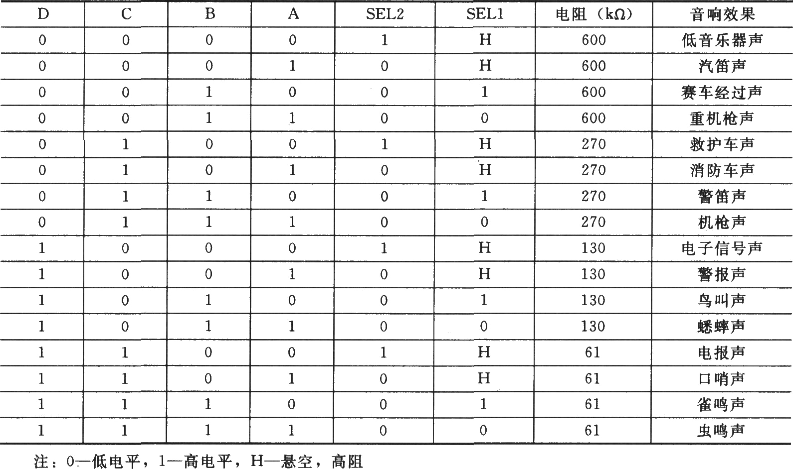
This chart – for a similar chip in the series – gives some idea of the variations in binary inputs, combinations of selection inputs and resistances that produce different sounds. If you read Chinese, which I don’t, it probably tells you in the right-hand column what sounds these combinations make.
The PCB was robustly constructed and I put it together omitting the four slide switches, as I intended to control it externally, and didn’t attach the piezo sounder, which wasn’t going to be used.
Several of the resistors, when tested, had an effect on the pitch and speed of the sounds – the main job of the 4066 and 4011 is to select different combinations of resistors to affect the sound produced, much as indicated in the chart above – so I picked the likeliest one and replaced it with a 1M potentiometer. This seemed to do the trick – perhaps taking things slightly too far in the upper direction, so I added a preset in series to keep it from going to its maximum – although it had happily done this without any danger of crashing the chip.
I only had a log potentiometer available, and in the end this was quite fortunate. I found that connecting it the opposite way round from what would be expected – i.e. turning it clockwise decreased the pitch and speed, rather than increasing it – exploited the logarithmic scale well, making a much slower and smoother transition through the higher pitches and speeds. I could have bought an ‘anti-log’ pot, but additional time and expense didn’t seem worth it.
This was a timely reminder that a useful part of experimentation would be to compare lin and log pots in particular situations, and reversing the log ones to see what difference this produced. (Reversing the linear ones would, of course, do no good, as they progress evenly through the scale from top to bottom, whichever way round they are).
This part of the circuit (the kit PCB) now looked like this:

The original circuit diagram was provided by the supplier, Chip_Partner_Store, a Chinese company with an eBay shop at http://stores.ebay.com/Chip-Partner-Store. Places like this – and there are many of them on eBay – are great for browsing through: you can find great deals on bulk buys of common components, as well as somewhat more unusual ones at very reasonable prices, and odd chips and modules like this one, which could always come in handy.
I’ve indicated in the diagram where I added the 1M potentiometer and preset, plus four LEDs, connected, via 470Ω resistors, to the A B C D inputs, the other ends connected to ground. These were not there for any reason, particularly, except as an indicator of the code being received – and on the principle established with Bigfoot that flashing lights are always good. I was sceptical as to whether the circuit supplying the four inputs would be able to power these as well as operate the Sound effect module correctly, but it all seemed OK.
The greyed-out section at the output wasn’t used in the final circuit.
Actually, this unit begins sounding repeatedly as soon as power is connected to it, since the default input 0 0 0 0 has an associated output – ‘Machine gun voice’ – and I couldn’t find a way of stopping it, so I also added a power on/off switch to this board, which isn’t shown, in case this feature became annoying.
*
SInce the circuit has four binary inputs, and I wanted to control the unit with the Bigfoot, which has a 4-bit binary output, it would seem logical to connect the Bigfoot output directly to the A B C D inputs.
Unfortunately, this wouldn’t allow the Sound effect module to be operated by the Stylophone keyboard, or the Bigfoot to control the Sound Machine, so additional circuitry was needed to convert the binary input into 16 individual outputs, and then convert that back into binary . . .
. . . Fortunately, the first of those would be a duplicate of part of the Bigfoot circuitry, which I was familiar with, using a 4067 chip. This part of the circuit looked like this:

The input from the 5-pin DIN socket goes first to a 4050 hex buffer. Four of the six buffers are used. The reason for doing this is to exploit an unusual and very useful feature which the 4050 shares with its more common sibling, the 4049.
Both perform a similar function, but the 4049 inverts the input (high level voltage in = low level voltage out, low level voltage in = high level voltage out), and the 4050 doesn’t.
What both of them are able to do is accept an input voltage level higher than the supply voltage, a vital consideration here as the output from Bigfoot is at 9v, whereas the circuitry of the StyloSound is at only 4.5v. The 4050 is able to acccept the 9v input from Bigfoot and safely reduce it to 4.5v for the other circuits. 9v isn’t a problem for CMOS chips, but the Sound Machine and the Sound effects module are both rated at 4.5 – maybe 5 or 6 maximum – volts.
The four outputs of the 4050 go into the A B C D inputs of the 4067. Each of the 16 outputs of the 4067 goes to the pole of one of the SPDT switches described earlier. According to the binary coding on the inputs, one of the 16 outputs of the 4067 is connected to +V, and this signal is sent in the direction either of the Sound Machine when the switch is to the left, or the Sound effect module when it’s to the right.
*
The Sound Machine has 16 separate inputs, so no further circuitry was required: each switch was connected to one of the 16 places on the Sound Machine PCB where there used to be buttons.
For this signal to operate the Sound effect module, however, it needed to be changed back into binary.
Fortunately, this change is not difficult to implement, using a pair of 4532 chips and a 4071. The 4532 is essentially the opposite of the 4067: it takes individual inputs and converts them to binary. Each one has only 8 individual inputs and outputs in 3-bit binary, but the datasheet showed this 16-input, 4-bit binary output circuit, which is the one I used:

The 16 inputs marked ‘From Stylophone Keyboard’ were all connected to ground with 100k resistors so that each one would be at 0v if not receiving a +V signal from the keyboard or the 4067. The outputs of the 4071 were connected to the Sound effects module where marked A B C D in the earlier diagram.
Here’s how the physical connections are made, and what the chips look like on the board:


I’m not entirely sure that the correct order of those 16 inputs is as implied in the datasheet circuit. Since I had LEDs on the inputs of the Sound effects module – i.e. effectively at the outputs of the 4071, I was able to check the sequence, and I found myself swapping some of them around. If you’re using this method of converting single outputs to binary, it would be advisable to check this as you go along. In my case, the wiring to and from the SPST switches was such a bird’s nest, that it became too difficult to work this out. If it becomes clearer when I use this system in future projects, I’ll make sure to record the correct sequence.
However, when tested with ‘Bigfoot’, the module was triggered accurately, and the LEDs on the input lit up with the correct numbers when the notes were tested with the stylus and keyboard.
*
So now I had two separate sound effect circuits which differed in several ways: the Sound Machine uses samples, which are played back in their entirety, and are particularly effective when slowed down; the Sound effects module produces electronic sounds from oscillators, which can be cut off and replaced at any time by another sound, and lend themselves to being sped up.
Both sections had separate pitch/speed controls; both could be controlled automatically by Bigfoot, or manually via the Stylophone keyboard.
*
I could have stopped there, but I had another idea which I thought could be included. I believe this is known in the trade as ‘feature creep’ – just adding that one extra implementation, which then turns into two, then three . . . and eventually makes a simple circuit over-complicated.
But I had just acquired a number of unwanted ‘Voice Recorder’ key rings – 100, in fact! – at a few pence each. At this price, they weren’t guaranteed to work, but when I tested some, quite a few seemed OK, and they were powered by 3 little coin cells – i.e. 4.5v, the same as the rest of the circuits in the StyloSound, so I thought I could employ a couple of them here.
Here’s what they look like:

There’s a very small microphone, a Record/Play switch, a button to operate whichever of the two functions it’s switched to, and an LED to indicate that it’s recording, as opposed to playing back. I thought it would be good to be able to record a small (up to 8.2 seconds, it said) burst of sound while the samples or effects were being manipulated, then be able to play it back precisely the same again, a primitive – but undeniably inexpensive – repeat/looping device.
So I added a couple of these, connected to the outputs of the Sound Machine and the Sound effect module. Small tactile switches glued to the front of the instrument replaced the ‘Record/Play’ switch and button, and I also moved the small LED’s to the front panel as well.
*
Only one thing remained, as far as the circuit was concerned, which was the output stage. This turned out to be . . . strange.
First of all, I needed to mix together the four outputs: the Sound Machine, the Sound Effects module and the two recording devices, as well as send the Sound Machine and Sound Effects module outputs to the inputs of the recorders. I planned to do this with a passive mixer – i.e. just join the outputs together with resistors.
The Sound Machine worked perfectly with the internal speaker, but the Sound Effects module would only work with the other speaker terminal connected to +V rather than 0v: otherwise, it was extremely quiet. I got round this by taking the output directly from the output of the LX9561 board, as indicated in the circuit diagram above, and bypassing the output transistor.
The outputs of the recorders were much too quiet, too, and the only way I could make them loud enough was to give them a path to +V by means of a very low value resistor (22Ω). The sound quality of these didn’t quite match that of the Sound Machine and Effects module – partly, no doubt, because of reduced bandwidth in the recorders – but they definitely added a useful function.
In fact, I had intended to add tone and volume controls at this point, but the device refused point-blank to make any sound if anything other than a very low value resistor was put in the output path, I don’t know why.
In the end, I used 22Ω resistors to join the 4 outputs (two in series for the Sound Machine, which was a little louder than the others) and ran this straight to the speaker and output socket. So, the final stage looked like this:

The resistors are all 22Ω, as opposed to some other equally low value, simply because I had a pile of them which were going spare.
So: strange, but when I plugged it into my mixer, it sounded fine, and the volume could be adjusted there.
*
The only thing left to do was to finish the case. There was so much internal wiring and circuitry that the case had to be made 2.5″ deeper. I constructed sides from an offcut piece of white plastic and superglued them in place – not especially neatly, it has to be said – with a little internal bracing.


 *
*