Note that in the following post I’m describing taking a hard drive apart in order to reuse some of the parts, but have no intention of putting it back together, or making it work again as a hard drive!
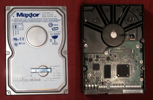
This the 3.5″ hard drive I took apart as my first experiment:
I’m sorry the PCB side is rather blurry, but I was less interested in that than what was inside.
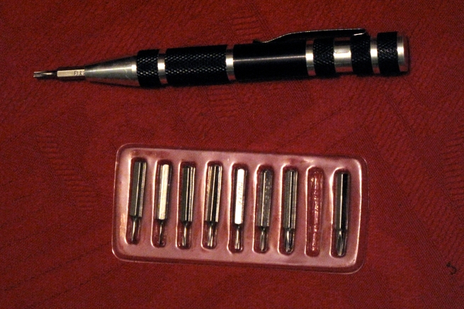
The tools required for the job were a small screwdriver set, from which I mostly used a Torx or ‘star’, which I think was size 8, and a very small Philips or crosshead for a couple of screws inside:
I also needed a large flat-bladed screwdriver, which I used two or three times. If you’re going to do the same, you may find a few differences in the details – type and positioning of screws, differently shaped fittings, and so forth, but the principles should be the same.
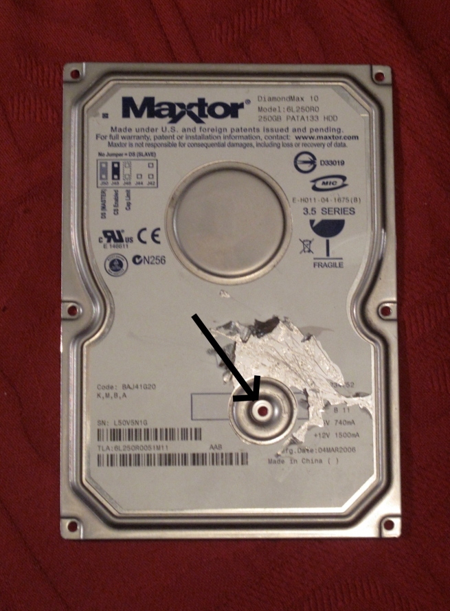
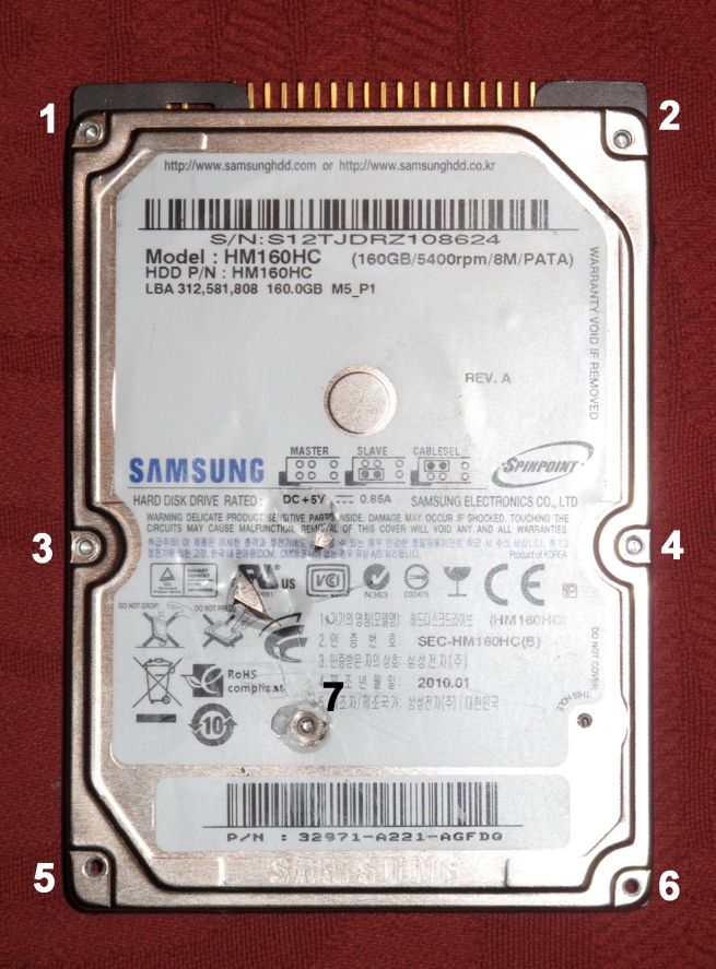
I first removed the circuit board, and put that aside. Turning it over, you can clearly see in the first picture the 6 screws round the edge of the ‘lid’ which needed removing.
Having taken these out, it seemed that the top was glued in place as well as screwed, so I went round with the large screwdriver, prying it open. This almost freed it, but it was only after still experiencing considerable difficulty in getting it completely open that I realised there must be another screw somewhere in the middle, under the label. I scraped away the label until I found it and took it out. The arrow shows where it was.
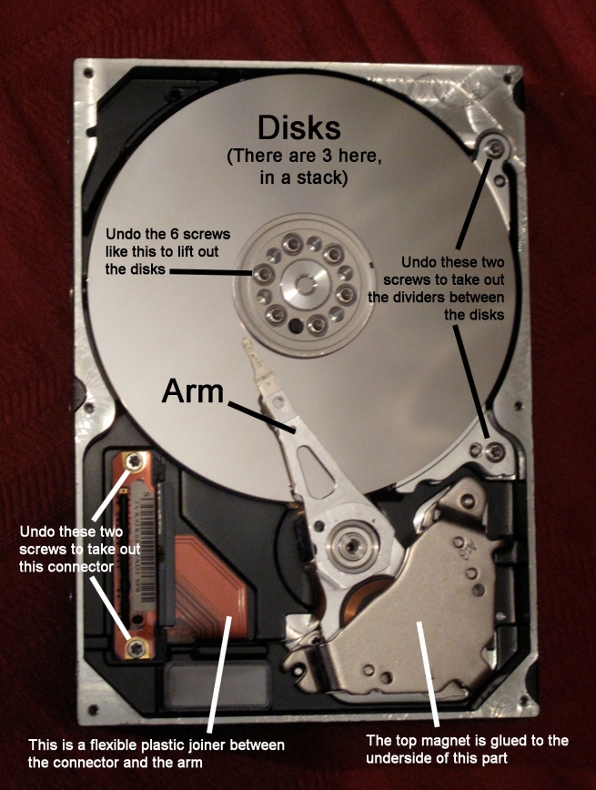
I was then able to take the lid right off and expose the inner workings – of which there aren’t actually that many.
The picture shows the disk or disks, one on top of the other, like a stack of pancakes – except there are gaps between them, and the arm is actually several arms, one for each disk; the arm itself with the delicate heads on the end which read the data from the disks, and with its other end moving between two magnets (not visible at the moment); and finally a flexible plastic multi-way ‘cable’ which joins the arm – and some small circuitry on the arm – to a connector. This would have poked through a gap in the case to connect to the circuit board on the other side.
Later on, connections will have to made to some very, very tiny points on the arm, and it’s going to be a lot easier to trace these points back to the connector, so its important not to damage the plastic cable. The connector could be poked out from the other side, once it two fixing screws had been removed.
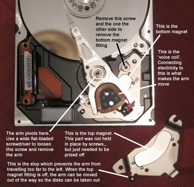
The fitting obscuring the back end of the arm wasn’t – in this model of drive anyway – screwed in place, it was just slotted on some pins and just needed prising off. I believe the magnets in hard drives are made of neodymium. This is classed as a ‘rare earth’ (although it’s isn’t actually any rarer than, say, copper) and makes very strong magnets. Just be a bit careful as you remove them, and think where you’re going to put them down as you can be surprised at how firmly they grab lighter metal objects.
This picture shows the top magnet fitting removed:
Once the top magnet is off, it’s possible to move the arm out of the way and get the disks out. This involves removing 6 screws around the centre (on top of the motor) and two screws at the side. the disks and the various fittings associated with them all come off in layers. The disks – there were three of them in this drive, look very much like CD’s, with a large hole in the middle, except they’re made of metal.
I put the disks carefully to one side – I had an idea they might be good for chimes or cymbals – and focused on the arm.
With the top magnet out of the way, it was possible to see the so-called ‘voice’ coil’. Two impossibly tiny wires connected the voice coil with the arm actuation circuitry, and to test that the arm was working I needed to attach a battery to these wires.
In the end these wires were just too small, so I traced them back through the plastic cable to the connector, where it was slightly easier to get at them. Attaching the battery leads to the two points produced nothing at 4.5v, but at 9v there was a loud and satisfying clunk, which showed that the arm was working fine.
*
The procedure with the next disk I worked on, a smaller 2.5″ was exactly the same. The top came off once I had removed the 6 visible screws and the 7th screw hidden under the label. I needed a smaller Torx/star screwdriver – a size 5 or 6 – for this disk compared to the other one.
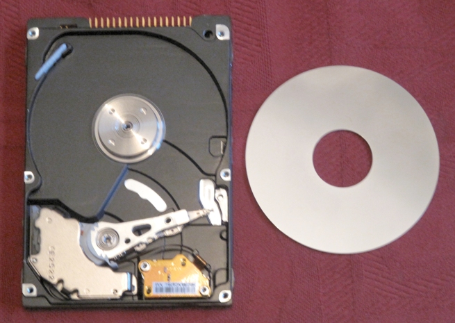
This exposed the single disk and arm:
A single screw in the middle of the motor housing allowed the disk to come out.
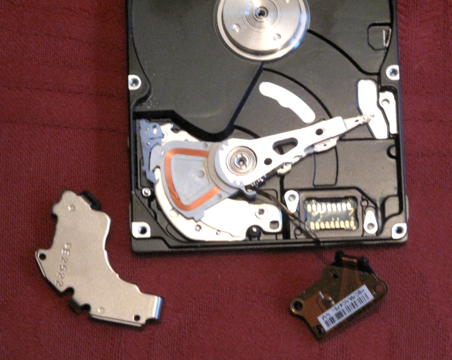
Removing two screws freed the unit in the bottom right, which connected the arm with the circuit board on the other side.
I prised off the top magnet (bottom left), just to make sure the construction was the same as the 3.5″ drive – which it was.
I replaced the magnet and tested the drive with a battery. I’d already removed a plastic retainer on the right, by the heads at the end of the arm; I also had to remove the plastic piece which you can see on the left, which was restricting the arm’s movement. However, once I had done this, applying 9v to the appropriate pins on the connector reliably operated the arm.
In fact, this smaller mechanism would also work with 4.5v, which was a useful discovery. If parts of the circuitry which would operate it had to be quite low – say, 5v – it could be handy if the arm would also work at the same voltage.
*
So, I had verified that an arm from an inexpensive broken hard drive could operate as an electrically-operate striker, like a solenoid; that arms from both 3.5″ and 2.5″ drives would work; that the 3.5″ drive arm would operate at 9v; and the 2.5″ drive arm would operate at 4.5v. It will be some time before I get round to the next part of this project, but the next thing will be to see how the arms could be set up to operate outside the hard drive housing.
