Archive for August, 2012

23
Aug
12

BigBoy BeatBox

You’ve got a Stylophone, you’ve got a Stylophone Beatbox – but don’t you sometimes wish the two could be combined into one instrument? . . .

Well, now that wish has become reality, with the ‘BigBoy BeatBox’: two great Stylophone products in one!

New Front IMG_1128

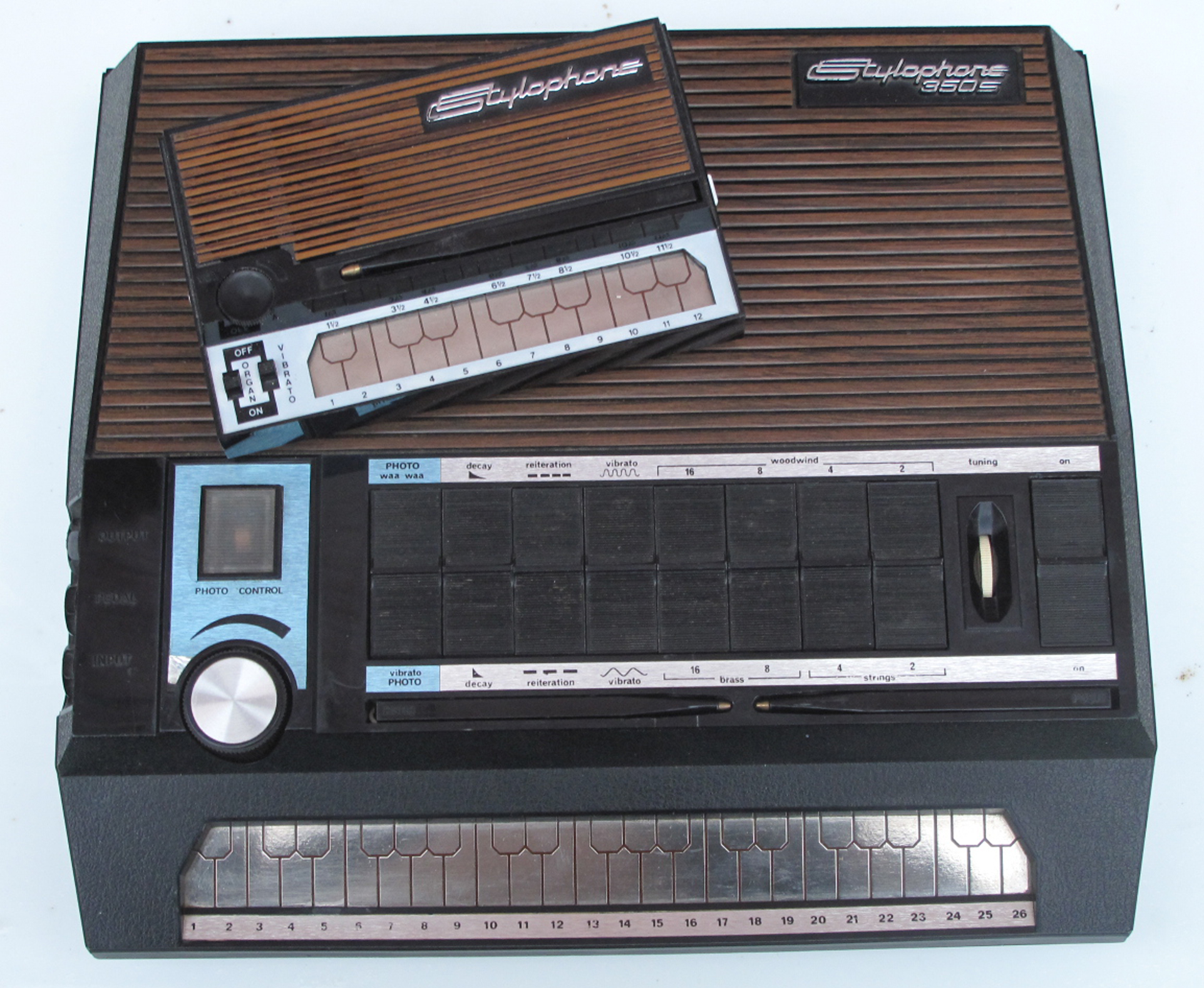
As the picture suggests, the BigBoy BeatBox is, in fact, two great Stylophone products literally glued and bolted together, with some of their internal circuitry combined.  The way it was created was like this:

1.  The Stylophone

The Stylophone half of the instrument is, in fact, a recreation of the original ‘Big Boy’ – a regular Stylophone S1 inside a Beatbox case.  As mentioned in an edit to the original post here, I managed to inflict terminal damage on the ‘Big Boy’ by reckless experimentation.  I normally do this before finishing an instrument, this time I contrived to do it afterwards . . . so the first thing I had to do was remove and replace the electronics with a new donor Stylophone I had lying around.

The actual process closely followed the construction of the original, but was made easier because of the sockets and wiring still remaining in the Beatbox case.  First of all, the end had to be sawn off the Stylophone circuit board, which is too long to fit in a Beatbox case; then the lowest 12 notes of the keyboard were connected to the 12 outside pads of the round Beatbox keyboard.  Fortunately, the wires attached to the Beatbox keyboard remained in the case, and just needed connecting to the appropriate Stylophone keys.  The Beatbox’s amp circuit board was taken out, but the Stylophone’s was kept and connected to the Beatbox’s speaker.  A power socket was connected to the Beatbox’s on/off switch, and the Stylophone’s on/off and vibrato switch circuit board disconnected.

I decided to replace the ‘Big Boy’s troublesome original 3-way octave switch with a simple  pitch potentiometer.  I used a 100k for  coarse tuning, in series with a 10k for fine tuning and a 100k variable preset to fix the highest pitch available.  Previous experimentation with Stylophones had taught me they have no objection to going down to very low pitches, but they cease to function – usually temporarily – if the pitch is taken up too high: on resetting, when this happens – by switching the power off and on – sometimes they will begin to work again, sometimes they won’t.

That’s what I did to the original ‘Big Boy’, and there’s no cure apart from throwing the circuit board away and starting again.  The likelihood of this happening is increased because I don’t just replace the tuning potentiometer pin-for-pin – the range of voltages available between the two pins the Stylophone uses isn’t wide enough for very large pitch variations, so I use only one of the pins that the original tuning potentiometer was connected to – the left-hand one – but connect the other one to +v.

The two new pitch controls were fixed to the front (the rounded end) of the Beatbox case, as was a replacement 10k log volume control.  The problem with the Stylophone’s original volume control was not that it wouldn’t work perfectly well, but that it would have had to be on the side of the case which I was intending to fix permanently to  the other Beatbox.

The original ‘Big Boy’ had no vibrato, but I decided the recreation should have a variable control, as fitted to the ‘Alien’, my first Stylophone modification project.  All this involved was connecting a 1M potentiometer instead of an on/of switch between the two vibrato connections next to the power connection on the main Stylophone circuit board.

Apart from an output socket and a switch to cut out the internal speaker, that half of the BigBoy BeatBox was done.

Stylophone half IMG_1132

2.  The Beatbox

The other half of the instrument was a plain Beatbox, with very little in the way of modifications.

(I don’t seem to have written specifically about the Beatbox in the blog, by the way.  Read the user guide here!)

The first thing I did to it was to replace the tuning potentiometer with a larger one of 100k (a direct pin-for-pin replacement this time), allowing for considerable slowing down and lowering of the pitch of the drums and other sounds.

I also followed an excellent example in this YouTube video: http://www.youtube.com/watch?v=xXdelnxXF7A to add buttons in parallel with the ‘Record’ and ‘Play’ pads normally operated by the stylus.  The trouble with the stylus-operated method is the delay in time between activating ‘Record’ with the stylus, and then using the same stylus to stop recording and begin playing the pattern you want to  be looped, as the loop begins the moment ‘Rec’ is selected.  With a small normally-open tactile switch as an alternative method of beginning and ending the recording period, you can be much more accurate as regards timing.

It’s worth mentioning at this point that, like the original Stylophone itself, the Beatbox comes in more than one variety, as far as circuitry is concerned.  I noticed two significant variations between the Beatbox I used in my ‘test to destruction’ phase, and the one that eventually found its way into the finished instrument: in one case, there was a tap from the battery compartment at 3v, which fed into the circuit (via the 3-way tone control) as well as the full 4.5v; and the layout of the circuit board was different.  As it happens, spots on the board marked ‘Rec’ and ‘Play’ were easily accessed in one case – the test unit – but not in the other – the one I was eventually to use.

In my experience, the Beatbox is a very delicate circuit, and it doesn’t take much to do something to it that will cause Record or Play to malfunction, or the output quality of the sound samples to degrade; so, proceed with caution, I’d say.

A third new button I added to this unit was ‘Reset’.  The Beatbox’s method of erasing an old loop and re-recording a new one is to switch the power off and on again.  The original power switch had to be removed as it was on the side of the case which was going to be fixed to the other Beatbox case – and there would, anyway, be a single power switch for both units: so the third button is a direct replacement for the Beatbox power switch, but now a normally-on, push-to-break, supplying power to the Beatbox side only.  To reset and re-record just takes a quick press and release of this button.

Finally, a new 10k log output volume pot was fixed to the front of the unit.

Beatbox controls IMG_1131

Beatbox halfIMG_1131

3  Joining the two halves

Superglue and two bolts was all that was required to physically join the two Beatbox cases, plus a couple of holes through which wires could pass from one side to the other.

The easiest way to connect the power seemed to be to detach the +v and 0v wires from the battery compartment on the Beatbox side and attach these to the original ‘Big Boy’ Stylophone side, which had a power input socket.

In the end I decided that whereas the battery compartment of the Big Boy Stylophone had to be removed – there was no room for batteries as well as the Stylophone circuitry – the one in the Beatbox could be used.  So I wired in a power cable which ran out of the back and was just long enough to reach the power socket in the other half.  In this way the instrument could be powered from an external source, or from internal batteries, and there was no need for a switch to change from one to the other.

The two 10k volume controls were taken to two individual tone controls.  I just wanted something fairly rudimentary, so I used a circuit from http://www.muzique.com/lab/swtc.htm called the ‘Stupidly Wonderful Tone Control’.  The component values I used were quite different – and I have no idea why – but the format of the circuit was more or less the same, and gave a little bit of variation to the tone.

After the tone controls, the two outputs were joined with 10k resistors to the original Beatbox volume control, and then the ‘Big Boy’ Stylophone amp circuit board.  This meant that the sound from both units was going to the ‘Big Boy’ half , and the volume and tone of each unit could be independently varied.  The input to the Beatbox amplifier was disconnected, and the speaker removed.

Now I had an instrument in a single conjoined case, with a single power supply and output through a single speaker or output socket.  There were two styluses and two keyboards, and – as I had hoped, but not expected with any confidence – both styluses work on both keyboards!  This means that both units can be played with a stylus in each hand, and quicker and more rhythmic patterns can be played.  I extended the wires to the styluses slightly to make sure they could reach right across both keyboards.

When using two styluses on the ‘Stylophone’ side of the unit, the ‘Beatbox’ side needs to be set to ‘Play’, otherwise that stylus will only work for a very short period and then not sound any more.  I haven’t timed the ‘very short period’, which might give a clue, but this is probably to do with the circuitry which regulates the maximum of 8 seconds (at ‘normal’ tempo) for which the Beatbox can record.

The complete circuit looks something like this:

BigBoy Beatbox circuit 2 Corrected sm

The following pictures show the inside of the instrument shortly before it was finished:

Inside Stylophone half with numbers 6 in IMG_1127

This is the ‘Big Boy’ stylophone half.

1 = speaker cutout switch

2 = socket for external 4.5v power source

3 = 3.5mm sound output socket

4 = Stylophone S1 circuit board with permanently soldered connections to first 12 keys

5 = socket for extra stylus, remaining from original ‘Big Boy’ design – not really needed now

6 = fine tune pitch control

7 = variable preset to prevent the Stylophone’s highest note from being too high and causing the circuit to malfunction

8 = coarse pitch control

9 = Stylophone volume control

Beatbox half with numbers 7 in IMG_1126

This the Beatbox half.

1 = the original Beatbox output and ‘mp3’ input sockets, no longer used

2 = Stylophone tone control

3 = Beatbox tone control

4 = Original Beatbox volume control, now master volume

5 = ‘Reset’, push to break switch

6 = wires going to ‘Play’ and ‘Record’ push to make switches mounted on top surface of Beatbox

7 = original Beatbox tempo switch, still in-circuit, but no longer used

8 = Beatbox pitch control

9 = Beatbox volume control

The features visible on the outside were these:

Front DSCF0003 3

Before finishing I gave the speaker grilles a coat of blackboard paint.  The reason I used blackboard paint was a) it was the only black paint I found in my garage not in a spray can, and 2) it gives a pleasing matt finish, but is more durable than water-based matt emulsion.

The rear of the instrument was sprayed black and the holes masked with painted material.

New Back IMG_1130Front & Rear View IMG_1129_30

22
Aug
12

Stylophones 3 – The Stylophone 350S, Part 1

A series on the Stylophone can only reach a climax with the mighty 350S!

The question of why the original Stylophone sold in its millions and became a world-wide success story, and the 350S didn’t, has long been debated.

According to http://stylophonica.com (‘The official home of the Stylophone’), it was ‘too costly, and lost the key uniqueness of the Stylophone itself, which was its small size and mass-market appeal’ – but it certainly wasn’t through of a lack of features.

You may be familiar with the Stylophone, but not the 350S: if so, then to start with, a run-down of its capabilities is required:

First of all, it’s certainly true to say that it’s much larger than the regular Stylophone – which is, after all, about the size of an inch-and-a-half thick postcard.  Here’s my 350S together with the regular-sized ‘New Sound’ Stylophone with which it shares many of its design cues:

350s + New Sound IMG_1050

The 350S is a souped-up Stylophone in every way: instead of the Stylophone’s 20 notes – an octave and a half – the 350S has 44.  That’s three and a half octaves, and you can see in the picture the difference in length between the two keyboards.

Not only that, the 350S has eight voices, as opposed to one (or even the S1’s three), and some of these are themselves in different octaves.

The voices are designated ‘woodwind’, ‘brass’ and ‘strings’.  In these days of sample-based synths, none of these sound terribly much like what they say they are, but they have the general qualities of these instruments – and, despite what you may read, one or two of them are quite like the distinctive tone of the regular Stylophone that we all know and love!

These voices are:

four ‘Woodwind’ voices pitched at four different octaves, and described (like organ stops) as 16′, 8′, 4′ and 2′;

two ‘Brass’ voices at 16′ and 8′; and

two ‘Strings’ voices at 4′ and 2′.

Because these voices are pitched at different octaves, from 2′ to 16′, in all no less than six and half octaves are available from the bottom of the keyboard to the top.  This is almost as large as a ‘professional’ 88-note synthesizer keyboard.  Up to two of the voices can be combined at any time, one each of the four octaves.

As well as this wide range of voices, the 350S has a variety of built-in effects.  Like the regular Stylophone, one of these is Vibrato – and two speeds are available, rather than one.

There is also a two-speed ‘Decay’ facility: as well as the usual Stylophone ability to hold a note as long as the stylus is in contact with the keyboard, when the Long or Short (actually, ‘short’ or ‘very short’) Decay button is pressed, the note will fade out while the stylus is still in contact.  According to the nicely-produced, LP-sized User’s Guide that comes with it, this enables the player to obtain ‘a percussive effect rather like  piano.’

350s rocker switches IMG_1053 sm

However, as can be seen from the above picture, this is only the beginning of the 350S’s abilities.

The fast or slow ‘Reiteration’ button (second from the left) can be used to imitate the sound of a banjo or mandolin, and the 350S even has a second stylus which is used to produce these effects.

Normally, whichever stylus is being used, the ‘regular’ or ‘reiteration’, it’s held in the right hand; but it’s possible to play two notes at once in reiteration mode by using the reiteration stylus with the right hand, and playing lower notes with the regular stylus in the left hand.  It doesn’t work the other way round, and it doesn’t work in ‘normal’ mode, i.e. without either the fast or slow reiteration switch pressed.

The white tuning control can also be seen in the above picture – handily placed on the front of the instrument, unlike its counterpart in the regular Stylophone, which is always hidden underneath.

The most unusual effect, though, has got to be this:

350s Photo control IMG_1052

Above the volume control is the 350S’s secret weapon – the ‘Photo Control’.  This device, operated with the player’s left hand while the stylus is wielded in the right, can be set to control the volume, amount of vibrato or low-pass filter cut-off point – acting as a ‘waa waa’.

On the side of the 350S, next to the Photo Control, are three 1/4″ mono jack sockets.:

350s sockets IMG_1051

While one of these is ‘sound in’ and another ‘sound out’, the middle one is a socket for a foot pedal that replaces the Photo Control – either because the player would prefer to control volume, vibrato or waa with their foot, or because the ambient light level is too low for the Photo Control to be effective.  A 50k – 100k potentiometer does the job, according to the User Guide.

My experience of light-dependent controls like this – and I’ve made a number of them – is that they are really only fully effective when quite a bright light is shining on them, which is not always the situation when you sit down to play.

Unsurprisingly, this magnificent machine requires a fair amount of juice, so it’s powered by not one, but two weighty PP9 batteries, connected in series to provide 18v of power to the 350S.  [Edit: but see notes below about powering the 350S].  The batteries are housed underneath the rear of the instrument:

350s back IMG_1056

The battery covers look as if they’re held in place by screws, but these aren’t really screws: they click into place when pushed, and just require a slight turn with a screwdriver or a thin object to loosen them.  (The User Guide suggests a coin, but in my experience modern coins are too thick to perform this function.  Maybe a 5p would do it).

This is the User Guide that came with the 350S:

p1

350sBooklet

Reliable information on when the 350S first came on the market, how many were sold, etc. seems hard to come by.  http://stylophonica.com says: ‘No more than a few thousand 350S’s were ever sold’; http://stylophone350s.com/ says ‘Dubreq, the manufacturer of the original Stylophone created and produced the Stylophone 350S beginning in 1971 . . . fewer than 3000 were ever produced’ and quotes a Ben Jarvis (son of Stylophone inventor Brian Jarvis and re-founder of Dübreq in 2003) estimate that only 200-300 working units are probably still available worldwide.

I’d be surprised if the numbers were quite this low, but they’re certainly not common, and those that appear on eBay in the UK frequently command in excess of £100, rarely less than £70. Stylophone350S.com in the States have access to a recently discovered cache of mint condition boxed examples, which are now on sale.  Their website tells the story of this amazing find.  [Edit: this site is now defunct, unfortunately.  I don’t know what happened to the mint condition 350S’s that were for sale there].

The back of the 350S is removed by undoing 4 large screws in the corners and two very small screws under the front, and reveals two printed circuit boards: a thin, narrow one at the front containing the keyboard and the resistor chain – not discrete resistors, but what I’ve previously called ‘resistor modules’, since I can’t remember what the proper name for them is – and a large, rectangular one with everything else on it, including potentiometers, sockets and switches:

Just opened IMG_1068

The circuit boards themselves come away quite easily: there are 4 screws, clearly visible in the above photograph, which hold the keyboard in place, and 6 similar ones for the larger board.  The volume control knob doesn’t need to be taken off – it fits through the hole surrounding it – but the plastic nuts on the three sockets need to be removed.

This is what the other sides of the boards look like:

Component side IMG_1070

Here we see the larger items across the middle of the board, from left to right: the three sockets, the volume control, the eight voice and effect switches, the pitch control and the on/off switch.  If I was an electronics expert, I could tell you what the rest of the components do; but I can’t.  I can only surmise that the round inductor next to the left-hand switch is to do with the waa circuit; the LDR (light-dependent resistor) to the left of that is the ‘Photo Control’.

LDR & Ind New IMG_1144

The black ‘hood’ that partly surrounds the LDR was slightly damaged when I came to look at it, and it’s quite possible that I did this myself when I opened the case.  It was easily repairable with a spot of superglue, but watch out for this if you’re looking inside yours.

The ferrite core inductor is a Mullard FX2236.  In this close-up you can see that mine looks a bit broken.  I don’t know enough about these things to know if this means it isn’t working properly, but, while by no means common, they can be found – perhaps more easily in the UK than elsewhere – so I shall certainly consider replacing it.

According to the experts at www.stylophone.com, under the heading ‘VITAL INFORMATION WHEN BUYING A 350S… PLEASE READ CAREFULLY!’, one of the components you can see here – which they describe as the ‘Amp-ic’ – is highly prone to failure.

The related website, the Stylophone Information Centre at www.stylophone.fsnet.co.uk says: ‘The circuit board carries an IC which controls sound output, and this component (long since obsolete) is the single- most likely cause of the 350S to break down. If this happens . . . the unit will only be heard if played through a separate amplifier, if at all.’

The symptoms to look out for are: ‘when the stylus is applied to the keyboard, only a very faint sound is heard (if even audible at all), which fades away rapidly . . . Even with the volume control turned up to max, the sound will still be very low – then quickly fall away. The user will then be left with a ‘dead’ 350S.’

The chip in question is this one – the black one with six legs in the middle of the picture:

MFC6070 New IMG_1145

It’s a Motorola MFC 6070, 1-watt power amplifier  – ‘designed primarily for low-cost audio amplifiers in phonograph, TV and radio applications’, according to the datasheet.

If you don’t know what a phonograph is, ask your grandad, he’ll remember them!  The use of this antiquated vocabulary confirms what is said above.  If you find the datasheet for this chip, it says ‘Device discontinued – consult factory’; if you try to buy one on the Net, you’ll mostly find specialist sites, dedicated to sourcing obsolete parts.

As a matter of fact, you can, at the time of writing, get one on eBay for about £20, but you aren’t going to want to do that: the problem doesn’t arise, apparently, just because 350S’s are now all old – it even used to happen to quite new ones.

Stylophone.com told me that ‘the original chips as fitted . . . were working very close to their breakdown point voltage-wise. Although theoretically all the chips supplied to them should have worked, Dübreq actually had to batch-test the chips to find those with an acceptable working voltage range, especially the maximum voltage’ (which is meant to be 20v). ‘We’ve seen some of these chips.’ they said, ‘ running extremely hot (basically too hot to touch) by simply switching the instrument on, before even playing a note.’

That’s not to say the MFC6070 was a particularly unusual part at the time – they were used all over the place, and even the venerable VCS3 synthesiser used one as a driver for its spring reverb circuit.  However, as the site offering VCS3 spares, http://www.synthi.com, says: ‘The Achilles heel of the VCS3/Synthi AKS are the now obsolete and ultra rare semiconductors that it uses’ . . .

This made me think twice about powering the 350S with a mains-powered adapter: the increased risk of overdoing the voltage and blowing the chip might not be worth it.  Dübreq themselves did apparently produce some 350S’s with an ‘adaptor socket factory-fitted’, but ‘this led to many of them blowing the chip.’

I’m not quite as worried as I was, however, as stylophone.com are now marketing a new module, the ‘Stylophone ACM’, which can be retro-fitted to an ailing 350S – or even to a working one, as a precautionary measure – to get round this problem altogether.

The circuitry inside this unit is not operating close to its limits, and makes it much safer to run the 350S from an 18v adapter.  (And if you buy a reconditioned 350S from stylophone.com, it will already have one of these in it).

[Edit: see comments from Christian Oliver Windler below relating to powering the 350S.  He concludes from his tests that the 350S could – and should – be powered at less than 18v, and preferably less than 15v.  Some of the above problems and their expensive solutions can thus be avoided.

As with the original Stylophone, by the way, there appear to have been various upgrades during the course of production, and it’s interesting to note that some of the components inside Christian’s 350S differ from those in mine].

As a matter of fact, this is not the only ‘obsolete’ component in the 350S.  Although the resistors, capacitors and transistors that fill the circuit board are not commonly used in new designs nowadays, they’re still readily obtainable; the round silver integrated circuit over on the right-hand side, just above the tuning control, isn’t.

AY15051 New IMG_1142

It’s a General Instruments AY-1-5051, and what it does is frequency division (presumably for the 350S’s different octaves) – the kind of thing modern CMOS 4000-series chips do with the greatest of ease.  There’s a description on this website: http://www.divdev.fsnet.co.uk/repair2a.htm of how one might make such a replacement (using the example of a 1960s Elka electronic organ).  All I can say it, it looks feasible in theory, but not something I’d want  to be faced with in practice – let’s hope this isn’t a part which is going to fail!

Returning to my 350s, it looked badly in need of a clean up.  There was a lot of dust inside it, and over the years the keyboard had got very dirty:

Corroded keyboard IMG_1072Dust and corrosion IMG_1076

The switches sounded OK – no crackling or intermittent operation, so I left those, and just cleaned the circuit board and keyboard.  The keyboard in particular needed attention from, in order, a soft brush, switch cleaner, WD40 and Brasso.   This seemed to do the trick, and it began to look shiny again.

I cleaned everything, including the switch rockers, the case and the tips of the styluses, and put it back together again.  It now looked much better, and sounded clearly and reliably on every note.

Outside after cleaning IMG_1091

In my next post in this series, I’ll take a longer look under the bonnet of the 350S and see what there is to see.

06
Aug
12

The UFO and the Shuttlecraft

The UFO is a simple device for controlling instruments with light-dependent resistor (LDR) controls, for example the Opto-Theremin described in an earlier post.

It started life as one of those battery-operated lights where you push on the top to switch it on and off:

I painted it silver, and added bits to make it more flying saucer-like, some LEDs that change colour slowly, and a 5-LED goose-neck lamp that I found in a local Poundshop.

The colour-change LEDs have no important function, but the brightness of the goose-neck lamp can be controlled with a potentiometer, and can thus be pointed at an LDR and used to vary – in the case of the Opto-Theremin – volume, pitch or filter cut-off frequency.  Here you can see the lamp and the potentiometer: I didn’t attach a knob as I couldn’t find one that looked more UFO-like than the knurled shaft:

UFO High Angle DSCF0029

The goose-neck lamp is meant to operate from a computer USB port, so plugs into a USB socket, with only pins 1 and 4 (5v and 0v) connected.  The battery holder in the lamp is designed for 6v, and therefore had space for 4 AA batteries, but I mostly use 9v, so I adapted it to take a PP3.  I restricted the potentiometer from putting the full 9v through the LEDs, in case it was too much for them.

The maximum voltage allowed for the color-change LEDs was 4.5v; there are 4 of them, so I connected two in series on one side of the dome, in parallel with two in  series on the other side.

UFO Back DSCF0032

I also added some extra 3.5mm mono sockets, as can be seen in the picture, as this is a system I use for distributing power.  When the Opto-Theremin is used in conjunction with the UFO, it can receive its power from there, rather than from a separate battery.

This picture shows the two being used together:

UFO and Optical Theremin DSCF0022

These pictures illustrates the soothing effect of the constantly changing colors:

UFO Colours

The ‘Shuttlecraft’ isn’t really an invention of my own: in fact, it’s just a multi-LED lamp on a headband, as worn by cyclists.  It appears here only because it’s an aid to playing the Opto-Theremin.  Because light levels are often too low to get the maximum variation in parameters controlled by LDRs, it can be useful to have extra light to hand: but when your hands are occupied playing the instrument, the next best place is on your forehead.

Shuttle DSCF0035

Although the UFO and the Shuttlecraft were created with the Opto-Theremin in mind, they could be used with any instrument (or effect) that uses an LDR – for example, my first Stylophone mod, the ‘Alien’, or the Stylophone 350S.


andymurkin

August 2012
M T W T F S S
 12345
6789101112
13141516171819
20212223242526
2728293031  

Enter your email address to follow this blog and receive notifications of new posts by email.