Archive for August 4th, 2017

04
Aug
17

The MIDI CPU Project – 2. The Software

At the end of my previous post on the MIDI CPU Project, I had completed the wiring and construction of the MIDI CPU box – apart from solving the small problem of the box not being big enough for its contents, that is! – and it was time to test it to see if it worked.

The additional feature of the MIDI CPU is that it depends on being suitably programmed in order to function the way you want it to.  I don’t necessarily want to go into great detail about the exact programming I did, but I thought it would be useful to describe generally how it’s done, if only to reassure anyone thinking of embarking on such a project that it isn’t all that difficult, and shouldn’t be an aspect of using a device such as the MIDI CPU that would put you off.

First of all, the method of programming is via the MIDI connectors, so here’s what you need:

  1. a MIDI/USB interface (mine is a very cheap M-Audio Midisport 2×2, quite old now, but works perfectly, drivers for mac and PC readily available on the internet, cost less than £10 on eBay).
  2. 2 MIDI cables, for ‘in’ and ‘out’ (remember – which I don’t always do! – that the ‘out’ from the MIDI CPU goes to the ‘in’ on the MIDI/USB interface, and the ‘in’ from the MIDI CPU goes to the ‘out’ on the MIDI/USB interface!).
  3. a USB A to B type cable if your MIDI/USB link is like the Midisport and doesn’t have one built in.
  4.  a suitable program for sending and receiving SysEx messages.  The one to use for the mac is SysEx Librarian, and for PC, it’s SendSX.  These programs are free and come with documentation, so are pretty simple to set up and use.  Being a mac user, I also used a companion program of SysEx Librarian called MIDI Monitor, which would allow me to see what messages were being sent back and forth from my laptop to the MIDI CPU, and a small PureData patch of my own to see a little more detail of what was in the messages.

Not only does the MIDI CPU come with a fully detailed description of the board and ways of wiring it up, it also has a comprehensive guide to programming.  In addition, there is plenty more advice on the Forum, which I referred to in my previous post.  Even though, as I said, the forum is due to close at the end of 2017, I believe there are plans to preserve it in some way, which would be a very good thing, as it’s a mine of information which would be useful in all kinds of projects of this type.

Essentially, the programming is done in SysEx, and SysEx messages have the following format: a Header, consisting of SysEx header (F0), Manufacturer (e.g. 00 01 5D), Device ID (e.g. 04) and Command (e.g. 01), then some message information, and a footer (F7).  All numbers are in hexadecimal format (i.e. 01, 02, 03, 04, 05, 06, 07, 08, 09, 0A, 0B, 0C, 0D, 0E, 0F, 10, 11, 12, etc.) – which caught me out once or twice, but I soon got the hang of  it.

If you’re writing your own SysEx messages, you may find this chart useful, with all the MIDI numbers in it together with their hex equivalents:

MIDI Note numbers in hex

*

The MIDI CPU programming guide gave a couple of examples of useful SysEx messages.  This one asks the MIDI CPU to send back a message with the current firmware version:

F0 00 01 5D 04 00 7D
00
F7

(it can be written on one line, but I’ve separated the sections so you can see the header, the message and the footer).

You can write your own SysEx messages using a text program like TextEdit, Wordpad, BBEdit, etc., but what SendSX and SysEx Librarian prefer is to use SysEx messages in a file format with the suffix ‘.syx’.

To help you with this the Highly Liquid site kindly provided an online tool for you – this is now on the Code and Copper site at http://support.codeandcopper.com/txt-to-syx/ – so all you have to is write your SysEx message in a text program, copy and paste it into the online tool, press ‘Convert!’, and you get your message back in .syx format, ready to send to the MIDI CPU.

txt to syx

So, first of all, this is what I did.  I wrote the firmware enquiry message F0 00 01 5D 04 00 7D 00 F7, as above, in a text file, which I was able to copy and paste into the online tool.  I got back a file which I downloaded and renamed something like ‘firmware_request.syx’, so I’d remember what it was for.

I added this to SysEx Librarian’s library, made sure to select the port on the Midisport 2×2 I was using, Port B, at the top of the SysEx Librarian window, and pressed ‘Send’.

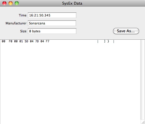
This is what SysEx Librarian’s window looks like.  The arrow in the top left is the ‘Send’ button:

SysEx Librarian window

The list of files in SysEx format which have been added to the Library are shown in this box.  Highlighting one and clicking the ‘Show File’ button at the bottom opens the folder in which the file is stored; clicking ‘Contents’ enables you to see what’s in the file:

SysEx Lib Bass Pedals.syx

After pressing ‘Send’ in SysEx Librarian, I could see with MIDI Monitor that a message had been sent, and a message had been received.

MIDI Monitor Firmware retrieval

You can double click on these messages to see what’s inside them.  The received message was very similar to the sent message, but with one extra piece of information.  It was all on one line, but I’ve separated the header, message and footer to show the new information in the middle:

F0 00 01 5D 04 7D
01
F7

The ’01’ meant that the current firmware version in the MIDI CPU I had bought back in 2010 was 1.1.  There haven’t been many updates since then but there was an important update between 1.1 and 1.2 which would affect my plans for octave up and down buttons, so I knew from this that I would first need to update the firmware – but the most important result of the message transfer was that I knew the device was working!

I’d downloaded the SysEx file from Highly Liquid for updating to firmware version 1.2a – and, in fact, it’s still available somewhere, as are later firmware versions – so the next thing was to send that message to the MIDI CPU.  This was a slightly more complex procedure, but the steps are laid out in the documentation.  I sent the (much longer) message, and when it was completed, sent the firmware enquiry message again.  This time it returned the information ’04’ in the middle, meaning firmware version 1.2a was now installed:

MIDI Monitor Firmware message

Following the guidance in the manual provided by Highly Liquid, I then wrote the most complex SysEx message, configuring each of the 24 control terminals.  Between the header line F0 00 01 5D 04 01 and the footer line F7, there had to be approximately 48 lines: one line for each terminal to tell it what to do on receipt of an ‘on’ message (a 0v pulse), and what to do on receipt of an ‘off’ message (a return to +v).  It was a little fewer than 48 as the terminals configured as potentiometers, modulation or pitch wheels just needed to be told to look out for a value beween 0 (0v) and 127 (+5v).

In this, my first scheme, the 24 terminals (0-23) were configured as follows:

0-12 were configured as on/off switches, producing a MIDI note on receipt of an ‘on’ message, and going silent on receipt of an ‘off’ message. (This scheme was created with the aim of producing a set of bass pedals.  These will operate the MIDI CPU via the 25-way connector, but the keypad buttons C, D, E, F, 9, A, O and B are also designed to produce notes for testing, tuning, etc.).

13 was configured as doing nothing.  (Its use will be seen in later schemes with more notes than a set of bass pedals).

14-16 were configured as latching on/off switches, for Hold, Sustenuto and Portamento.

17-19 were configured as momentary switches for octave down, octave restore and octave up.

20-21 were configured as potentiometers to control velocity and the amount of portamento.

22 is a ‘spare’ control, which can be routed by the ‘Select’ switch either to a spare latching switch (7 on the keypad), a spare momentary switch (8 on the keypad), a spare potentiometer, or the modulation wheel.  The programming will decide which of these is to be used; in this scheme I decided initially to configure it as a modulation wheel.  What exactly is modulated by this wheel always depends on the individual synth patch.

23 was configured as a pitch wheel control.

I originally wrote the text file like this, to remind myself  of some of the important details in it:

SysEx Text file

Afterwards, before I could use it, I had to remove all the comments on the right-hand side.  So then it looked like this:

Bass Pedals SysEx text file

which I copied and pasted into the online SysEx file creator.  I downloaded the .syx file, renamed it something like ‘Bass_Pedals.syx’, and sent it to the MIDI CPU.

The moment of truth came when I pressed some of the letter buttons on the lower keypad.  MIDI Monitor showed that the right notes were coming out:

MIDI Monitor Note on_off

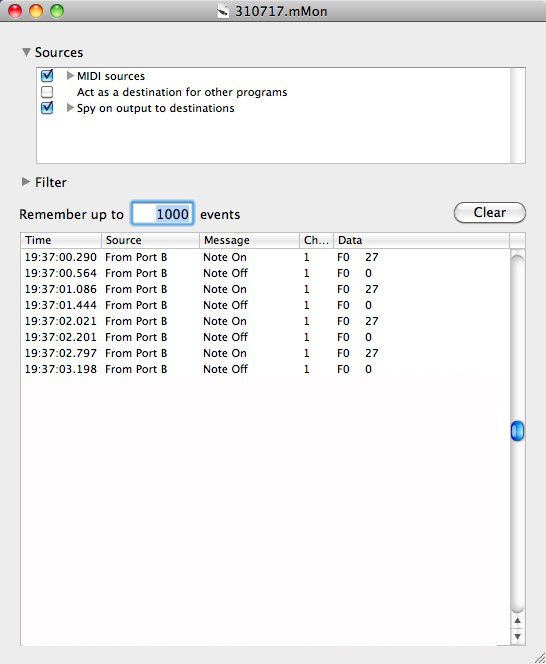
(Note that a ‘Note off’ message is actually a ‘Note on’ message, but with a velocity of zero.  I had the velocity control turned down rather low, at 27 – it would normally be much higher than this).

I used my PureData patch, ‘MIDI Tester’, to check a bit more closely what was going on:

MIDI Monitor NotesIt’s possible to see from the set of figures on the left that the MIDI channel in use was set to 3 by the MIDI channel control knob.  The velocity is 0 as this is always shown when you let go of the key (or keypad button, in this case), but I was able to check as I pressed down that moving the velocity control altered the velocity all the way from 0 at the left-hand end through to 127 at the right hand end.

The figures in the middle show that the first latching switching, ‘Hold’, had been turned on.  127 is on, 0 is off.

There was something wrong with the octave buttons, though – according to MIDI Monitor, which showed me the note names, they were clearly raising and lowering the pitch by more than 12 semitones . . . it took me a while to work out that I had written ’12’ in the SysEx message, but the hexadecimal number ’12’ means 19, so the buttons were raising and lowering the pitch of the notes by an octave and a half, not just an octave.  I quickly rewrote the text message with ‘0C’ in place of 12, got a new .syx file online and resent it to the MIDI CPU, and all was well.

I tried using the internal MIDI/USB interface instead of the Midisport, but although it basically worked, it seemed, according to MIDI Monitor, to be outputting some spurious messages as well as the intended ones.  Consequently, I’m not sure if this can be reliably used – only further testing can confirm this.  It wouldn’t be much of a loss if it didn’t work – the commercial device the board came from was very cheap, just a couple of pounds, it didn’t take much effort to wire it into the box, and the Midisport isn’t currently being used for anything else.  It would just be more convenient if a board within the MIDI CPU box could be used, rather than an additional external one.

Just before I finished, and while the PureData MIDI Tester was still open, I connected the MIDI CPU box directly to the laptop with a USB cable and pressed all the buttons on the upper keypad.  These produced the numbers 1, 2, 3, 4, 5, 6, 7, 8 and 9, and the letters i, o and p, as intended, so that part of the project had worked, too.  I envisaged that some applications of the MIDI CPU would be connected with PureData patches, so having these 12 input symbols available, in addition to the MIDI data, could be useful.

There are also 3 sockets on the rear of the box connected to the Apple keyboard PCB, so an external device connected via the 25 way socket could also be connected one of these if the numbers and letters were also required in addition to the MIDI.

The next post in the series describes the construction of the bass pedals.

04
Aug
17

The MIDI CPU Project – 1. The Hardware

I should have done this project 5 years or more ago!  However, illness, retirement and moving house all conspired to delay my progress.

When I finally came to put into action the plans I had drawn up in 2010, when I bought the module I’m about to describe, I found the device had been discontinued and support was about to cease – a great shame, because Highly Liquid, the company that made the MIDI CPU, were second to none in their support of every type of hobbyist and constructor who used their products (they made some other great devices, too), and their forum was – well, still is, until the end of this year (2017) – a mine of information.

So, my description of my endeavours is unlikely to help anyone embarking on the same project, but it might, on the other hand, be of interest to someone attempting something similar.

[Edit: also, see below for further information on the possible continued existence of the MIDI CPU and other Highly Liquid products (including the MIDI widget, which is the opposite of the MIDI CPU, i.e. a MIDI decoder).  There is a connection with codeandcopper.com, which is run by the same guy, John Staskevitch, and which is home to his current projects].

First of all, then, the MIDI CPU – what is it?

This is what it looks like:

midi-cpu-large_zyevag

It’s a small board, about  7 or 8cm long by 3 or 4cm wide with sufficient components to function as a MIDI controller.  Exactly what kind of MIDI controller depends on you: each of the 24 control terminals along the top edge of the board in the picture above can be programmed via SysEx to perform various logic or analog functions – i.e. they can be configured as switches for notes, switches for MIDI control messages, inputs from potentiometers, pitch and mod wheels, and so forth, whatever your application requires.

The 8 connections on the right-hand side are jumpers to set the MIDI channel, if you don’t want to have to set this as part of the programming.  The 4 pairs of connections are marked 1, 2, 4,and 8, so connecting them to +v or 0v like a binary number will set the channel.  Leaving them disconnected is effectively 0000, binary zero, or channel 1; connecting all of them is 1111, binary 15 (8+4+2+1), or channel 16, and so on.

The 5 connections at the bottom right are MIDI in and out, so the MIDI CPU can be connected to a computer and other MIDI equipment via conventional 5-pin MIDI sockets.

As I say, it’s sadly not being marketed any longer by Highly Liquid, although I see the boards, firmware and detailed information do now appear on circuithub.com and github.com, so it might be possible to obtain one after all, even if you have to solder it together yourself.  It seemed to me at the time an ideal purchase, due to its simplicity and versatility.  The cost was reasonable, around £40, as I recall.  I elected to make it a little more complicated than it needed to be, but you could, with minimal external wiring, create quite a complex MIDI instrument with it – 24 control terminals is plenty for a switch matrix, mod wheels and various other controls.

*

So, what did I do with it?  Well, I had alluded before, in my post on ‘A new use for USB keyboards‘, to a MIDI project which was going to fill up the rest of the enclosure which then included – amongst other things – the PCB out of an old Apple keyboard, and the MIDI CPU was this project.

Some buttons and modulation wheels would be built into the box, but essentially the MIDI CPU board would be accessed via a 25-way socket on the back of the enclosure, so any one of a number of different devices could be attached, and the MIDI CPU could when necessary be reprogrammed to allow for different uses of its control terminals.

*

MIDI CPU inside

This is what the enclosure looked like when I left it, and I now set about filling the top half with the MIDI CPU board and associated circuitry.

The first thing I wanted to do was to add pitch and mod wheels, buttons and potentiometers.

For the potentiometers I used the type with an integral press switch – if the external unit plugged into the 25-way socket had its own, I wanted these to be able to be taken out of the circuit.

For the pitch and mod wheels I bought a set off eBay which originally came from a DX7 or some such.  These were pre-wired and ideal for the purpose – the pitch wheel was properly sprung to return to centre – and were only about £10.

pitch & mod wheels

Conscious of the space problem, I decided on an unusual solution for the buttons: a 16-button keypad.  Although this looked like any keypad, internally it was rather untypical.

Keypads are normally arranged in a matrix pattern, so the output leads are ‘Column 1’, ‘Row 1’,  ‘Column 2’, ‘Row 2’ etc., and each button is in a unique position at the junction of a particular row and column; but this was a special design where each of the 16 buttons, when pressed, was simply connected to a common input.  I connected the common input to 0v, so that a button, when pressed, would be able to ground one of the MIDI CPU’s control terminals.  This is the signal the terminals need to be activated.

As far as momentary button presses were concerned, this was ideal, but to create latching switches – switches that stayed on until pressed again – extra circuitry was necessary.  What I used was a system with 4 ‘flip-flops’, plus a few signal inverters to make sure the flip-flop would be activated by a positive pulse, but the MIDI CPU control terminal would be activated by a negative pulse.  There were to be 4 latching switches, so 4 circuits like this were needed:

Latching switch circuit

Each of the circuits uses half a 4013 flip-flop chip, and half a 40106, which has 6 inverting gates altogether.  The input to the inverter on the left is kept high, so the output of the 4013 is kept low; the inverter in the middle keeps the MIDI CPU control terminal high, and the inverter on the right keeps the anode of the LED low.  In this way the MIDI CPU control terminal and the LED are both off until the switch on the left is pressed; when the switch is pressed the 4013 output changes state, the MIDI CPU control terminal and the LED are both switched on, and stay on until the switch is pressed again and the 4013 changes state again.

I added a 4-way switch so that all the latching buttons could be taken out of circuit if the external unit plugged into the 25-way socket had its own, or didn’t need them.

Finally, I wanted to add a MIDI channel selector switch, rather than rely on  programming to provide the channel, or hard-wire the jumpers on the MIDI CPU board (described above) to fix the channel permanently.

I got this idea from the Highly Liquid Forum.  The selector switch I used was a type of rotary encoder – specifically a hex encoder, which had 16 positions, and 4 outputs, which could output a binary number in each of these 16 positions, going from zero (0000) to 15 (1111).  (I had used one of these before, in creating the Bigfoot automatic stylophone controller).

The beauty of using this particular type of encoder – and they aren’t all the same, by any means – is that each of the 4 outputs is connected to a common terminal when it’s set at 1, but not connected when it’s at 0.  At the beginning (0000), none of the 4 outputs are connected to the common terminal; at the end (1111), all of them are; and in between (e.g. 0101) some of them are and some of them aren’t.  If the common terminal is connected to +v, then the 4 outputs can all be inputs to electronic switches, turning on when set at 1, turning off when set at 0.

A suitable electronic switch is the 4066, which has 4 switches in one chip, just right for the 4 connections which need to be made on the MIDI CPU board to change the MIDI Channel anywhere from 0 to 15, which represents the full number of MIDI Channels 1 to 16.

I also wanted to add an indicator of what MIDI channel was currently set.  To do this I used a chip which you’ve seen me use before, the 4067.  As luck would have it, this chip also requires a binary number from 0000 to 1111 as its input, and for each of these 16 different inputs it connects one of its 16 different outputs to a common terminal.  So, in this case I made the common terminal +v – via a small resistor – and connected 16 LEDS from the outputs to 0v.  In this way, as the MIDI channel changes, a different LED is lit up – no need for them all to have their own resistor, as only one of them will ever be lit at one time.

The simple, but effective circuit, looked like this:

MIDI Channel Selector

*

I then needed to connect everything together, and the quantity of components and wires in the  enclosure – as so often with my projects – began to increase rapidly.

IMG_0387 IMG_0388 IMG_0390

The keypad with the white buttons is the keypad I was describing above; in the first configuration I made of the MIDI CPU’s control terminals, the keys with letters play the appropriate notes of the scale: A, B, C, D, E and F; O plays A#/Bb, and 9 plays G; the other 8 numbered keys are divided between latching and momentary switches.

The keypad with the black buttons is not part of the MIDI CPU project: it’s connected to the USB keyboard PCB shown in the first picture of the inside of the enclosure above.  The numbers and letters it produces are useful in applications created with, for example, PureData, where the input can be interpreted in many different ways, as required.

The pitch and mod wheels can be seen on the left and the 16 MIDI channel indicator LEDs on the right.

*

In this view of the partially complete project, you can see 1. the MIDI channel circuit; 2. the MIDI CPU board; 3. the pitch  and mod wheels; and 4. the latching switch circuit.

Interior

The MIDI CPU board needs at this point to be connected to the MIDI in and out sockets and the 25-way socket for the control terminals, and the two keypads need to be connected to the USB keyboard PCB (upper keypad) and the MIDI CPU board (lower keypad).

*

I finished all the remaining interior connections, and the inside now looked like this:

Inside

I removed the excess wiring from the MIDI to USB board (removed from a commercial product, as described in the earlier post linked to above), which is now tucked under the long Apple keyboard PCB on the left-hand side; but the extra wiring from the MIDI CPU board to the internal switches and potentiometers and the external 25-way socket had still over-filled the enclosure!  This view from the outside makes it even more apparent that the box wasn’t going to close:

Back

So I was going to have to do something to make the interior larger before the unit could be used!

Nevertheless, every part of the circuit was now connected up, and it was going to be possible to test it.  I gingerly connected power and switched on.  Lights appeared – a blue light for power, indicator lights where potentiometers were pressed down for on; very bright lights in the centre where latching switches were on; the ‘MOD’ light, to indicate that the ‘Select’ switch for the ‘spare’ control terminal was turned to the modulation wheel position; a light in the MIDI Channel indicator column on the right, and – most crucially – the ‘Activity’ light (not yet labelled, but above the ‘power’ LED), connected directly to the MIDI CPU board, flickered on power up to indicate that it was ready for action.

Front

There was no instrument connected to the 25-way socket – I haven’t yet made any! – but there were enough controls on the box to test a good deal of functionality, including note on and off information from some of the keypad buttons.

Part 2 of this series describes the software, programming and testing of the MIDI CPU box.


andymurkin

August 2017
M T W T F S S
 123456
78910111213
14151617181920
21222324252627
28293031  

Enter your email address to follow this blog and receive notifications of new posts by email.