In the course of creating alternative keyboards, and interpreting USB inputs, I had an idea for a project which could prove to be useful.
It occurred to me that the computer was able to recognise the input from QWERTY keyboards because of the chips and circuits inside the body of the keyboard – the actual switches themselves, how they were laid out, what exactly they represented, were irrelevant. So, if you had access to the circuit board inside the keyboard, and left the USB connection intact, you could do what you liked with the switch connections.
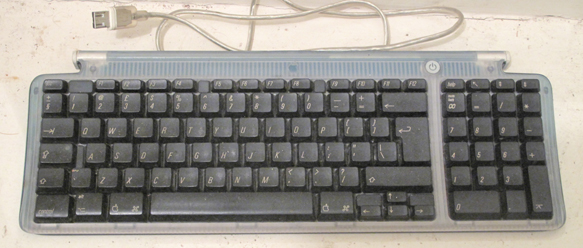
The keys of a QWERTY keyboard are arranged in a matrix – I had no idea how many connections there would be in each axis, and it probably differs from one model of keyboard to another. But I had an old Apple keyboard I was about to throw out because of sticky keys, and I decided to experiment on this.
Here’s what I did:
First of all, I took it apart, threw away the casing, put the switches to one side, and detached everything from the circuit board, except the USB lead.
As it happens, the circuit board in this keyboard is unusually large – covering the whole width of the keyboard, and with extra USB sockets on each end. Normally, the mouse would be plugged into one of them – and they aren’t the same: the one with the lead attached is the one that has to be connected to the computer.
The extra USB connectors on the ends of the board would probably be useful later, but more important was the circuit board itself. Here you could see the two series of tracks for the two different axes of the switch matrix.
In theory, each track in the first series – which I called Series A – would give a different output when connected to each track in the second series – Series B. There was only one way to find out: I plugged the USB lead in to the computer, opened Word, and got to work with a lead and crocodile clips.
If I remember correctly, I had to scratch off the track surface a little to get a good contact, but starting on the left I clipped the lead to the first track, A1, and progressively touched the other end to B1, B2, and so on, noting in a table what letters or symbols appeared. When I reached the end of the Series B tracks, I reattached the lead to the second track on the left, A2, and repeated the procedure, touching each of the tracks in Series B and noting the results.
Not all the combinations seemed to work, but eventually I produced the following table:
This list seemed to contain all the letters of the alphabet and all the numbers 0-9, so I considered this a great success!
It seemed to me that tracks 1, 2, 4, 5, 6, 7, 9, 10, 11 and 12 in Series A, and tracks 2, 3, 4 and 11 would be the useful ones – 14 connections giving 40 outputs. It wouldn’t matter what kind of switches were used to make the connections, their output would be predictable and the ASCII codes they produced could be interpreted reliably by programs such as Pure Data.
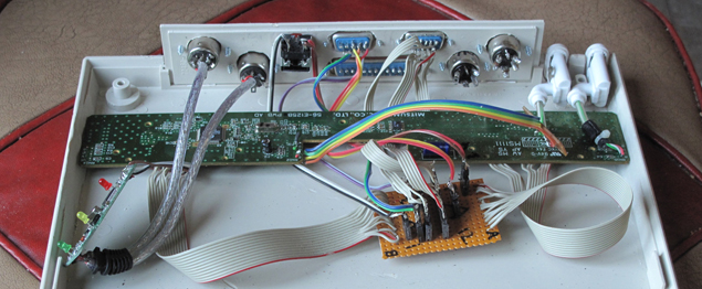
All I had at this point was a circuit board with a cable attached to it, so I decided to put it in a permanent box. I had a suitable one to hand, which it would just fit in, and decided to use this, together with sockets on the rear connected to the 14 tracks. I gingerly soldered ribbon cables to the two series of tracks, and this photograph of the inside of the box shows how it looks:
You can see the leads from Series A on the left-hand side and the leads from Series B on the right-hand side, leading to a circuit board with PCB connectors. These are connected to 3 different sockets on the back of the box.
There are 3 sockets because I decided that not every potential application would require the full 40 connections. There’s a 15 way DB15 HD socket (the type used for VGA) for any application requiring the full 14 connections (10 x 4 matrix covering all the letters A – Z, numbers 0 – 9, and a couple of others); a DB9 socket for applications requiring only 7 or 8 connections (4 x 3 or 4 x 4 matrix, e.g. a numeric keypad); and a 4-pin socket (the type used for S-Video) for an application requiring only 4 connections in a 2 x 2 matrix.
The original circuit board, as described above, had a hard-wired USB out lead and a USB A socket on each end. As you can see from the above pictures, I took off the hard-wired output lead and replaced it with one of the sockets from one end of the board. I know you’re supposed to have USB B, not USB A sockets in this position, but it’s easier to come across USB A to USB A leads, and the functioning is still the same.
The large DB25 socket, and the two 5-pin MIDI sockets on the left are for a future project, not yet finished, for a fully-featured MIDI controller. I’ll describe this in a later post, when I get round to constructing it.
I also bought a supply of leads, ready for when external switching devices need to be attached. In some cases this was easier than others. I chose these formats partly for the availability and inexpensiveness of the leads, but was unaware that the 15-pin HD leads commonly seen are designed for VGA or S-VGA, which don’t have all 15 pins connected one-to-one. In the end I found the ones I needed, but if you’re doing the same kind of thing, take care.
The final thing to note is the circuit on the left-hand side of this picture:
Although not strictly necessary at this stage, I decided to add this feature while I was working on the box. The MIDI controller, planned to be in the same enclosure, would need a USB converter in order to be attached to the computer. The only USB converter I have at the moment might be required in future for another device, so I decided to add a MIDI to USB converter to this box, which the MIDI controller could use if necessary.
I took a chance on a cheap MIDI converter, which was £5 on Amazon.
I had read bad reports of these things, but they’re so cheap compared to the brand name converters, I thought I’d see what they were like. You can get them for even less than £5, direct from China. When I got this one, I took the circuit board out of its plastic casing, chopped off the the in/out leads and rewired them to the sockets on the back of the project box. It was powered via USB, and appeared to work fine with my Sonuus G2M Guitar to MIDI converter, so I took the final step of cutting off the USB lead and attaching the USB output to the spare USB input on the Apple keyboard PCB. (It was spare because, as mentioned above, I took the socket off to create a new USB output socket instead of the hard-wired lead).
It still worked, so I put the lid back on the box, and called it a day on that project for the time being. When I get round to creating some alternative switching devices, or start on the MIDI controller, I’ll post something on them.
A brand of keyboard with a smaller PCB would probably be more practical, and any keyboard will do, if you want to try it yourself. There’s an excellent video on YouTube, here: www.youtube.com/watch?v=a3NxQ60E72k, which goes through the steps very clearly.
It just so happens that I saw a job lot of broken Apple keyboards for sale like the one I used here and bought them for about £1 each, so I’m stuck with these for future experimentation! The faults they had were various – sometimes it seemed to be the circuit boards, sometimes it was just the odd key, so all of them looked usable in one way or another.
I may not need the circuit boards – although I could make self-contained instruments if the cases were big enough to hold them – but I have plans for the keying mechanisms, which could be interesting.


